5-10-5 Constant Speed Arrival Signal (FA1)
•
This signal is output when the output frequency reaches the frequency set in the Output Frequency
Setting/Monitor.
In F001, the frequency reference selected at that time is displayed.
•
Allocate one of the Multi-function Output 11/12 Selection (C021/C022), or Multi-function Relay Out-
put (AL1, AL2) Function Selection (C026), to 01 (FA1).
•
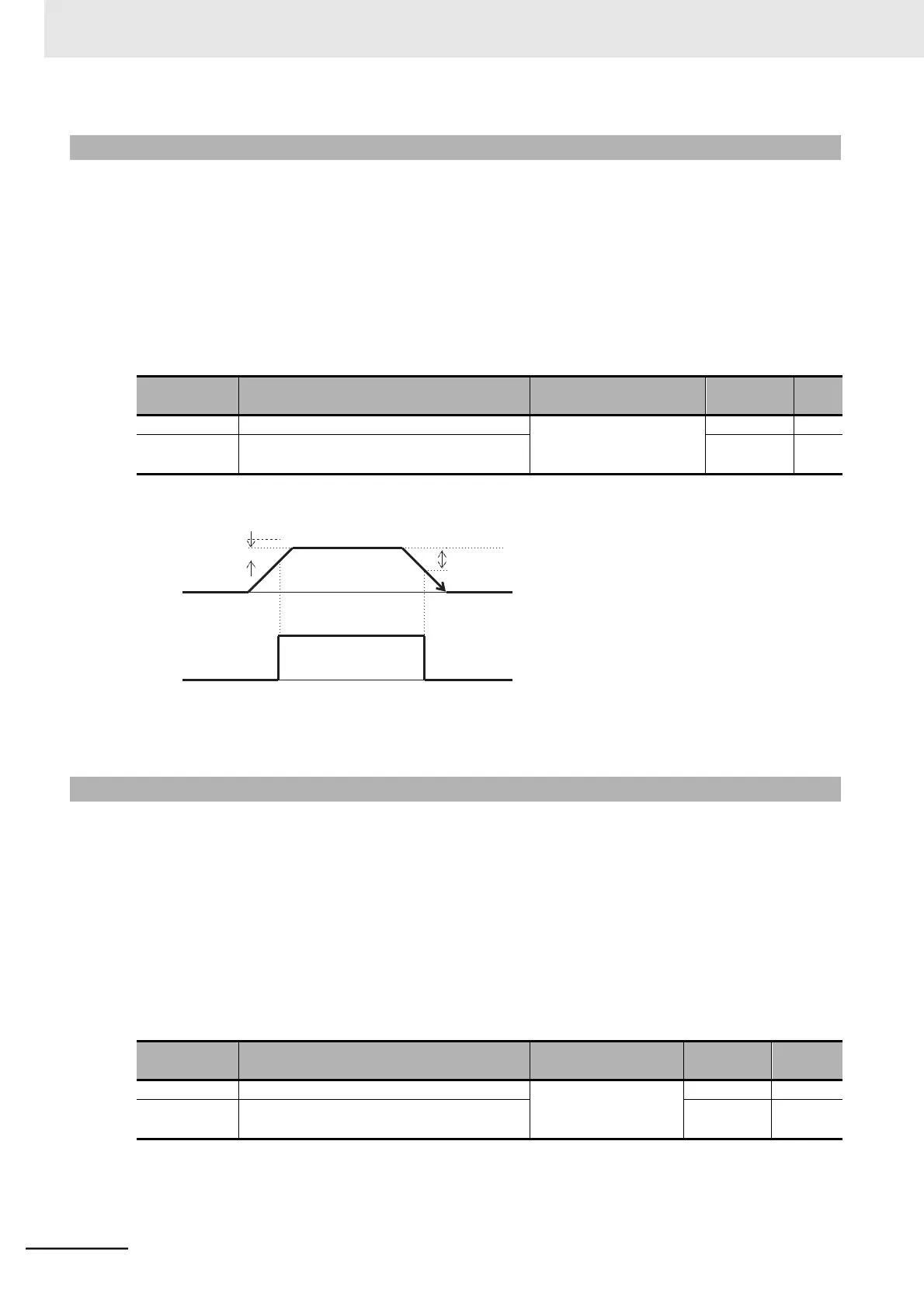
The hysteresis of this frequency arrival signal is calculated as follows.
ON (fon) : Set frequency − 1% of maximum frequency) [Hz]
OFF (foff) : Set frequency − 2% of maximum frequency) [Hz]
Output
frequency
fon
foff
Set
frequency
fon: 1% of maximum frequency
foff: 2% of maximum frequency
FA1
Example
Maximum frequency = 120 [Hz]
fon = 120 0.01 = 1.2 [Hz]
foff = 120 0.02 = 2.4 [Hz]
Set frequency = 60 [Hz]
During acceleration: FA1 is ON at 60 - 1.2 = 58.8 [Hz]
During deceleration: FA1 is OFF at 60 - 2.4 = 57.6 [Hz]
5-10-6 Alarm Signal (AL)
•
If an overcurrent, overvoltage, or some other error occurs, the inverter shuts off its output and outputs
an alarm signal (AL). This is called a “trip.”
•
A trip state can be canceled by resetting the inverter, by which the alarm signal is also turned OFF.
To reset the inverter, press the STOP/RESET key on the Digital Operator or turn ON the reset termi-
nal. However, you cannot reset some trip factors by using these methods. In such cases, cycle the
power supply.
•
Allocate one of the Multi-function Output 11/12 Selection (C021/C022), or Multi-function Relay Out-
put (AL1, AL2) Function Selection (C026), to 05 (AL).
By default, the Multi-function Relay Output (AL1, AL2) Function Selection (C026) is set to 05 (AL:
Alarm signal).