8-8 Co-inverter Communication
In addition to the standard Modbus communication (slave), the 3G3MX2-EV2 Series Inverter provides
the co-inverter communication function, which enables more than one 3G3MX2-EV2 Series Inverter
to communicate mutually without master equipment such as a computer or PLC.
In co-inverter communication, the inverters are assigned as “management inverter,” “master inverter,”
and “slave inverter”. The master inverter is specified by the management inverter according to the user
settings. The others are slave inverters. The management inverter is always fixed, but the master
inverter is switched sequentially. Therefore, the management inverter may serve as the master or a
slave inverter. Other conditions are as follows.
•
One management inverter is required within a network.
•
Up to 8 inverters can serve as the master inverter.
•
Up to 247 inverters can be connected within the entire network (32 inverters without repeaters in
compliance with the RS485 specifications).
In co-inverter communication, be sure to assign the station No. 1, which serves as the management
inverter.
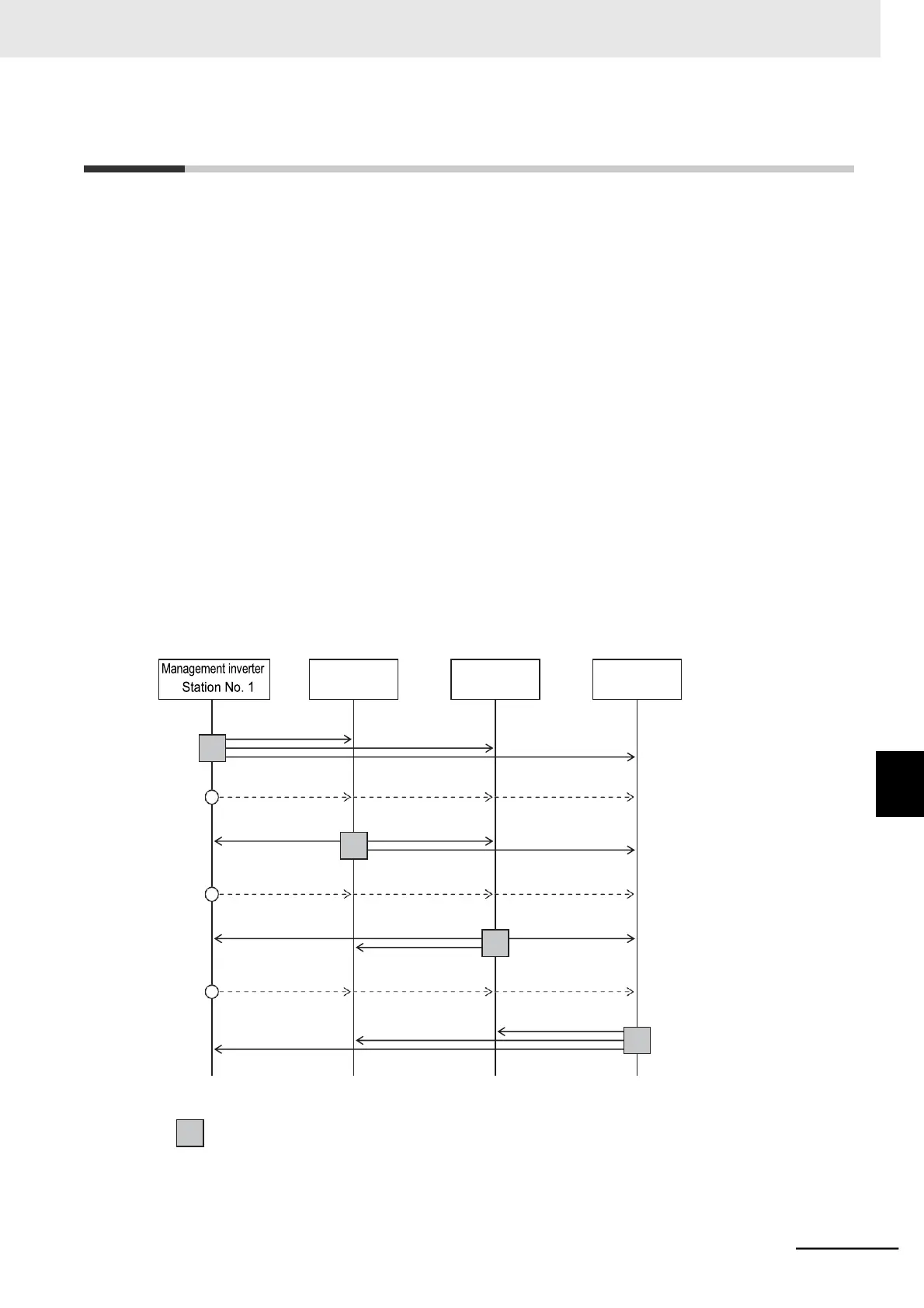
The master inverter can write data to the holding registers on any slave inverter. At this time, up to five
different station numbers and holding registers can be specified at once. On completion of each data
transmission session between the master and a slave (or slaves), the master inverter is switched to the
next in a sequential manner. In this way, data transmission is repeated according to the settings for
each master inverter.
Master (Inverter No. 1) sends
data to slave(s).
Master is switched from
Inverter 1 to Inverter 2.
*1*2
Master (Inverter No. 2) sends
data to slave(s).
Master is switched from
Inverter 2 to Inverter 3.
*3*4
Master (Inverter No. 3) sends
data to slave(s).
Master is switched from
Inverter 3 to Inverter 4.
Master (Inverter No. 4) sends
data to slave(s).
: Master inverter
*1. Switching of the master is performed automatically by the management inverter.