Multi-function Compact Inverter 3G3MX2-EV2 User’s Manual (I666-E1)
3-1 Operation of Digital Operator
The Digital Operator is a display operation panel for the 3G3MX2-EV2 Series Inverter.
3-1-1 Part Names and Descriptions
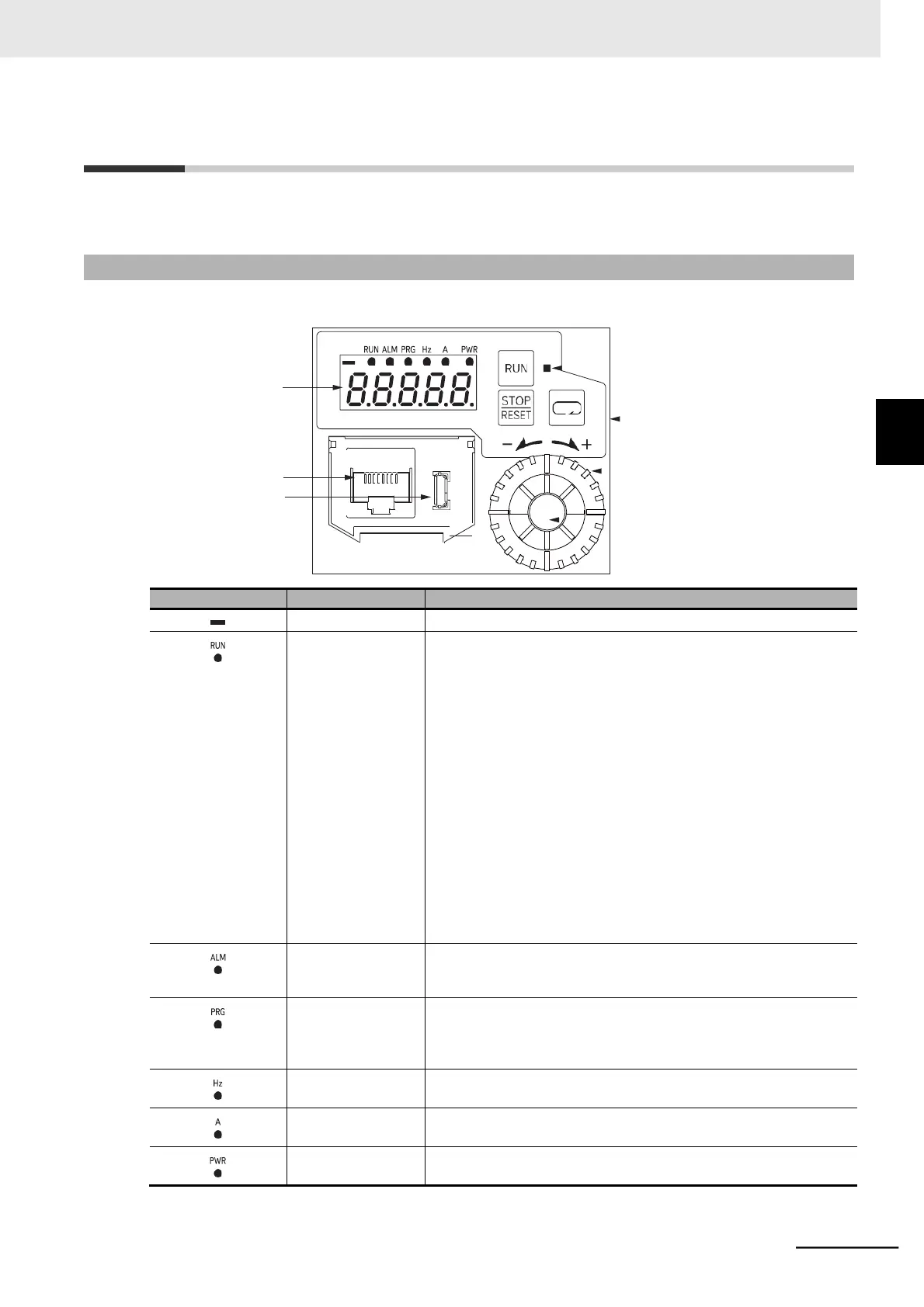
The table below shows the name and function of each part of the Digital Operator.
LED data display
RJ45 connector
USB connector
RUN key enabled
LED indicator
Operation keys
Jog dial
Enter key
Lights (in red) when a negative value is displayed on the display.
RUN (Operation)
LED indicator
Lights green when the Inverter is operating.
The indicator also lights when the Inverter is decelerating after the
RUN command is turned OFF since the it lights when one of the fol-
lowing conditions are met: “RUN command is input” and “Inverter
output is ON.”
The indicator blinks green if the RUN command is input when the
inverter is not ready for operation. When the reset is released, RUN
will light up.
• Frequency reference of 0 Hz
• Trip occurred
• Inverter is reset
• STO is active
• Free-run command is input
• Permission of RUN command is OFF
• Free V/f Frequency 7 is less than 30
• Parameter inconsistency warning occurred
Lights red when the Inverter has tripped.
For how to reset a trip state, refer to How to Reset a Trip State on
page 10-3.
Lights green when the data display shows data (a set value) that
can be changed.
The indicator blinks when the set value is inconsistent. Refer to
10-1-4 Warning Display on page 10-11.
Monitor LED
indicator (Hz)
Lights green when the data display shows a frequency.
Monitor LED
indicator (A)
Lights green when the data display shows a current.
Lights green when the Inverter is supplied with power.
3-1 Operation of Digital Operator
3-1-1 Part Names and Descriptions