Multi-function Compact Inverter 3G3MX2-EV2 User’s Manual (I666-E1)
RUN key enabled
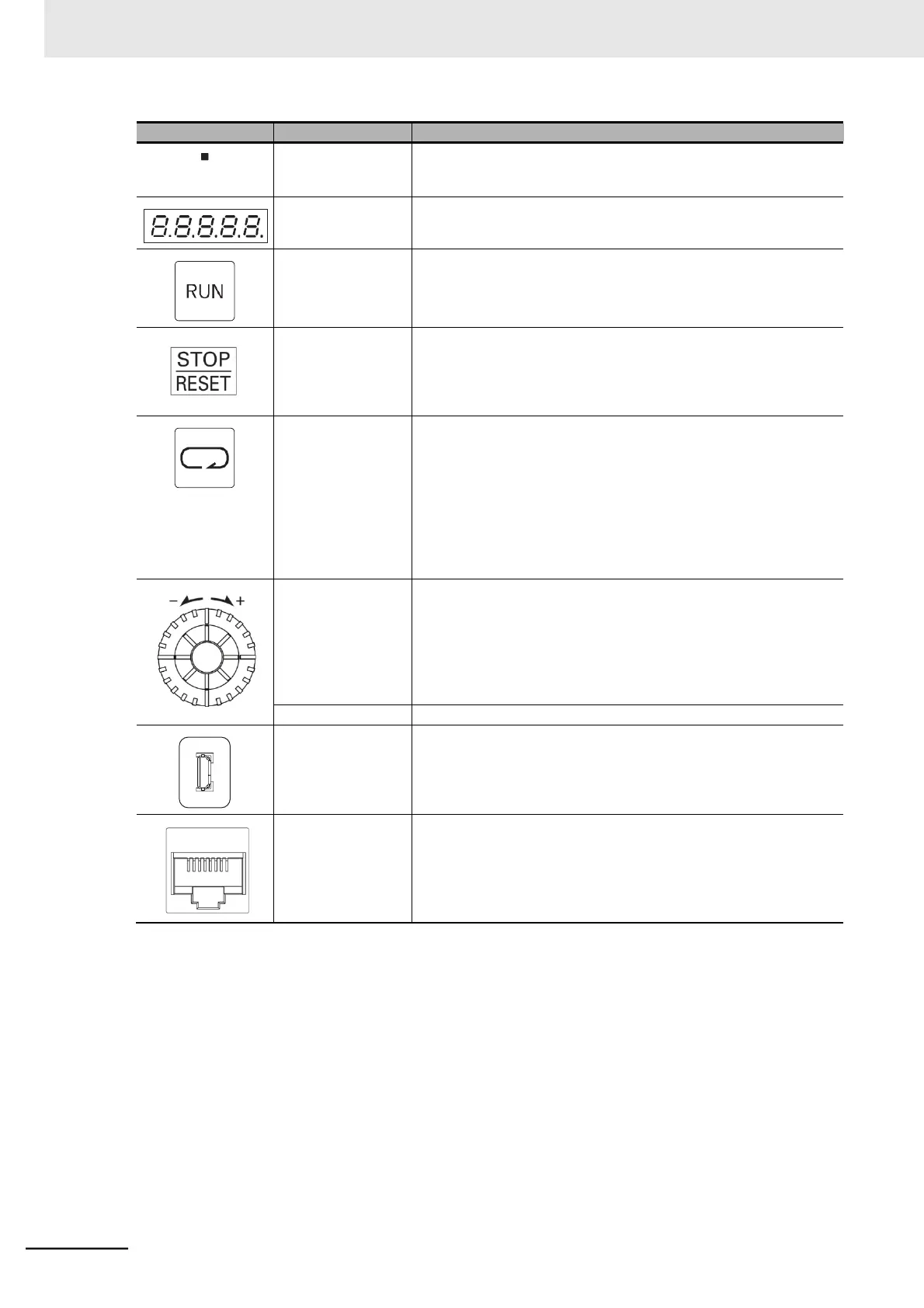
LED indicator
Lights green when the RUN Command Source Monitor (d063) is set
to Digital Operator. This indicates that the RUN key is enabled on
the Digital Operator.
Displays (in red) various data such as a parameter value, frequency
value, or set value.
Starts the Inverter. This key is enabled when the RUN command is
set to Digital Operator.
Decelerates the Inverter to a stop.
The STOP/RESET key is enabled when the RUN command is not
set to Digital Operator. However, you may disable it by setting the
parameter b087.
When the Inverter has tripped, the trip state will be reset.
When parameter is displayed: Moves to the beginning of the next
function parameter group.
When data is displayed: Cancels the setting and returns to
the parameter display.
When the Digital Operator (Model: 3G3AX-OP01) is connected,
press and hold this key for 3 seconds or more to move the operation
to the Inverter’s Digital Operator. Press and hold the key again for 3
seconds or more to move the operation back to the Digital Operator
(Model: 3G3AX-OP01).
In parameter display mode: Switches to the data display.
Press and hold this key for 3 sec-
onds or more to enter the individual
input mode.
In data display mode: Enters and stores the set value
(into the EEPROM) and returns to
the parameter display.
Increases or decreases the parameter number or the set data value.
The Micro-B type connector for connecting a computer.
Used to connect to the Inverter/Servo support tool CX-Drive
The connector (RS-422) for connecting the optional Digital Operator
(Model: 3G3AX-OP01). Once you connect the Inverter to the Digital
Operator (Model: 3G3AX-OP01), the built-in Digital Operator keys
will be disabled. In this case, set the data displayed on the display in
b150.