11-1-5 Megger Test
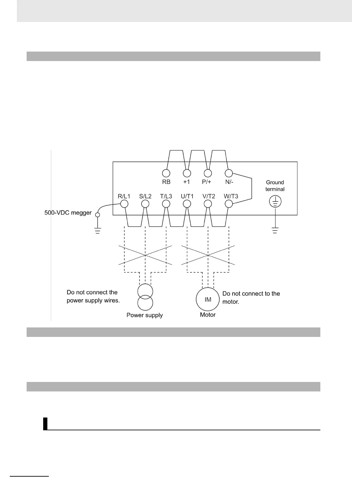
Before performing a megger test on external circuits, be sure to disconnect all the terminals of the
inverter and not to apply the test voltage to the inverter. Use a 500 VDC megger for a megger test.
For a megger test on the inverter main circuit, short-circuit the terminals R/L1, S/L2, T/L3, U/T1, V/T2,
W/T3, RB, +1, P/+2, and N/− with wires, as shown below.
Because the insulation resistance rating of the single inverter unit is 5 M or higher, it is normal if the
resistance is 5 M or higher.
•
For the inverter, do not perform a megger test on the control circuit. Perform it only on the main cir-
cuit.
•
Use a tester (in a high resistance range) for a power-on test on the control circuit. Do not use a meg-
ger or buzzer.
11-1-6 Withstand Voltage Test
Do not conduct a withstand voltage test on any part of the inverter.
Doing this test is dangerous because it may cause damage to or deterioration of the parts inside the
inverter.
11-1-7 Inverter/Converter Unit Test
Use the following procedure to check conditions of the inverter and converter units by using a tester.
1 Disconnect the externally connected power supply wires (R/L1, S/L2, T/L3), the motor
connection wires (U/T1, V/T2, W/T3), and the regenerative braking resistance (P/+, RB).
2 Prepare a tester. Use the 1 resistance measurement range.