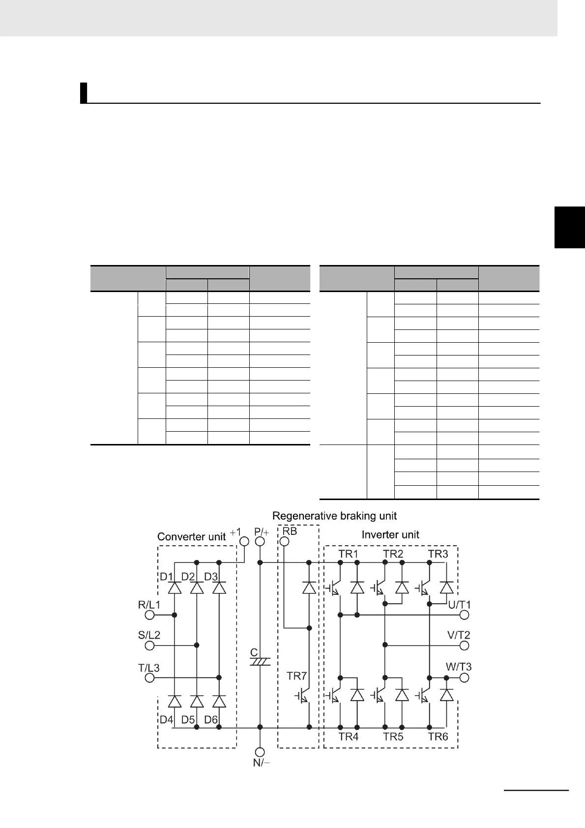
Measure the resistance at the inverter main circuit terminals block R/L1, S/L2, T/L3, U/T1, V/T2, W/T3,
RB, P/+2, and N/− by alternating the polarity of the tester to judge the conduction state.
•
Before starting the test, measure the voltage between P/+2 and N/− in the DC voltage range to check
that the smoothing capacitor is sufficiently discharged.
•
The tester will show nearly infinite resistance in a no-conduction state. (With conduction, the tester
will show a resistance from a few to several tens of .)
However, it may not show infinite resistance if a momentary conduction is detected due to the influ-
ence of the smoothing capacitor.
The inverter or converter unit is in good condition if the measured value for each item in the following
table is nearly equal, although it does not match exactly because of the element type, tester type, and
so on.