Multi-function Compact Inverter 3G3MX2-EV2 User’s Manual (I666-E1)
5-9-2 Multi-function Input Operation Selection
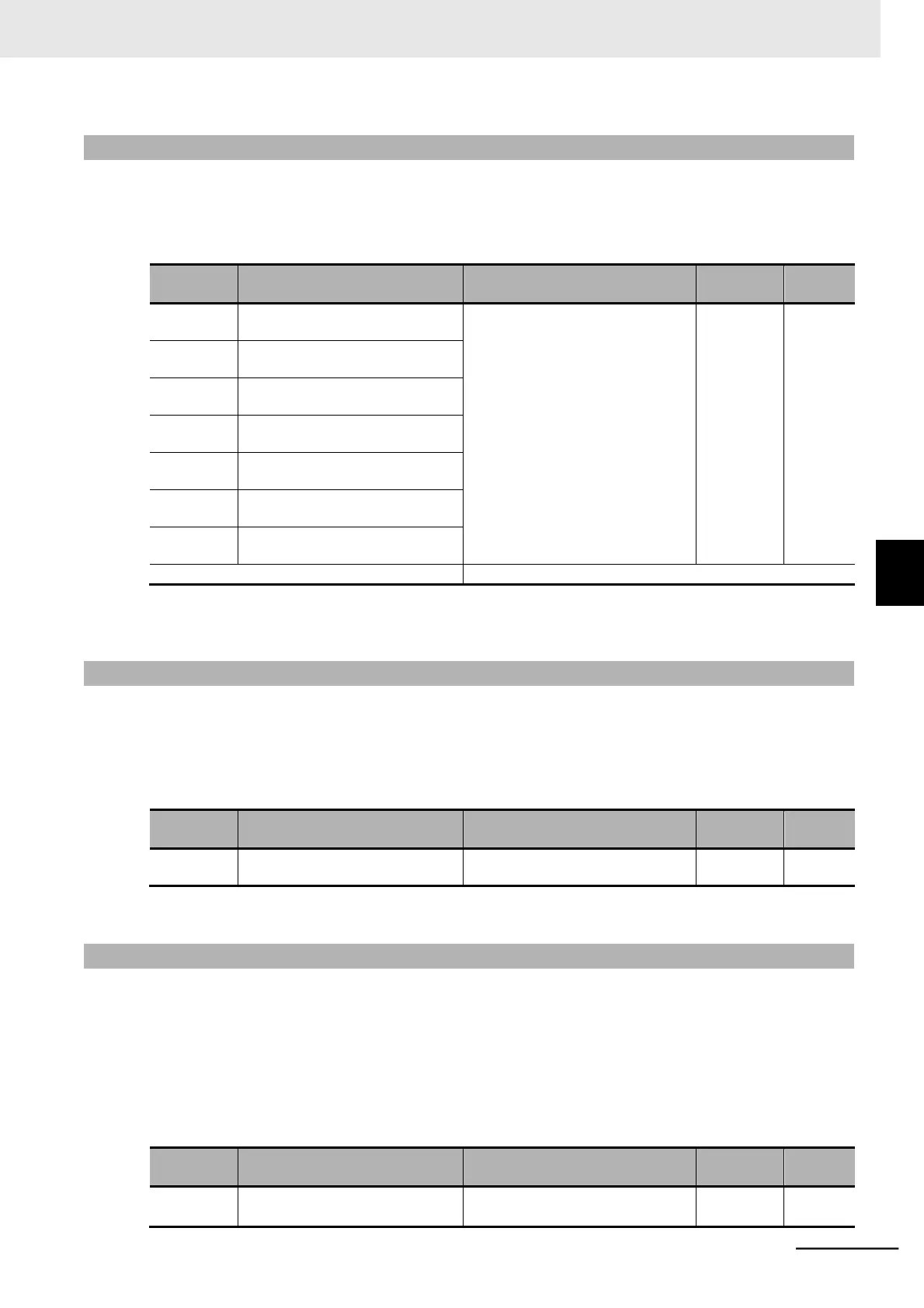
The multi-function input terminals can be set to either NO (NO contact) or NC (NC contact) individually.
This manual describes each function with the Multi-function Input 1 to 7 Operation Selection (C011 to
C017) set to 00 (NO: NO contact). Note that the operations of set signals are reversed when you set
them to 01 (NC: NC contact).
Multi-function Input 1 Operation
Selection
00: NO (NO contact)
01: NC (NC contact)
• Each multi-function input termi-
nal 1 to 7 can be set indepen-
dently to either an NO contact or
NC contact input terminal.
*1
• The terminal allocated to 18 (RS:
Reset) cannot be set to NC
contact. Be sure to set the NO
contact.
Multi-function Input 2 Operation
Selection
Multi-function Input 3 Operation
Selection
Multi-function Input 4 Operation
Selection
Multi-function Input 5 Operation
Selection
Multi-function Input 6 Operation
Selection
Multi-function Input 7 Operation
Selection
*1. NO contact: ON when closed, OFF when open
NC contact: ON when open, OFF when closed
5-9-3 Input Terminal Response Time
•
Set the response time for each multi-function input 1 to 7 terminal independently.
This function is effective for removing noise caused by chattering etc.
•
If the terminal input becomes unstable because of chattering, increase the set value.
However, increasing the set value results in a slow response.
The setting range is 0 to 200, which provides a response time of approximately 2 to 400 ms.
Multi-function Input 1 to 7
Response Time
*1. When 0 is set, the response time is 2 ms.
5-9-4 Forward RUN Command (FW) and Reverse RUN Command (RV)
•
To input the forward and reverse RUN commands via the control circuit terminals, set the Multi-func-
tion Input 1 to 7 Selection (C001 to C007) to 00 (FW) and 01 (RV).
•
By default, the Multi-function Input 1 Selection (C001) is set to 00 (FW) and the Multi-function Input 2
Selection (C002) is set to 01 (RV), respectively.
•
To input the RUN command via these control circuit terminals, set the 1st/2nd RUN Command Selec-
tion (A002/A202) to 01 (Control circuit terminal block).
•
If the terminals FW and RV turn ON simultaneously, the inverter will stop without displaying any
alarm. It will start operating again when either of these terminals turns OFF.
Multi-function Input 1 to 7 Selection
00: FW (Forward)
01: RV (Reverse)
5-9 Multi-function Input Settings
5-9-2 Multi-function Input Operation Selection