*1. For a broadcast, no response will be sent back.
*2. Note that the coil address is 0000, which is 1 less than the coil number 0001: Coil address = Coil number - 1.
If the Write to Coil function is not executed normally, refer to 8-5-9 Exception Response on page 8-20.
8-5-4 Write to Holding Register [06 hex]
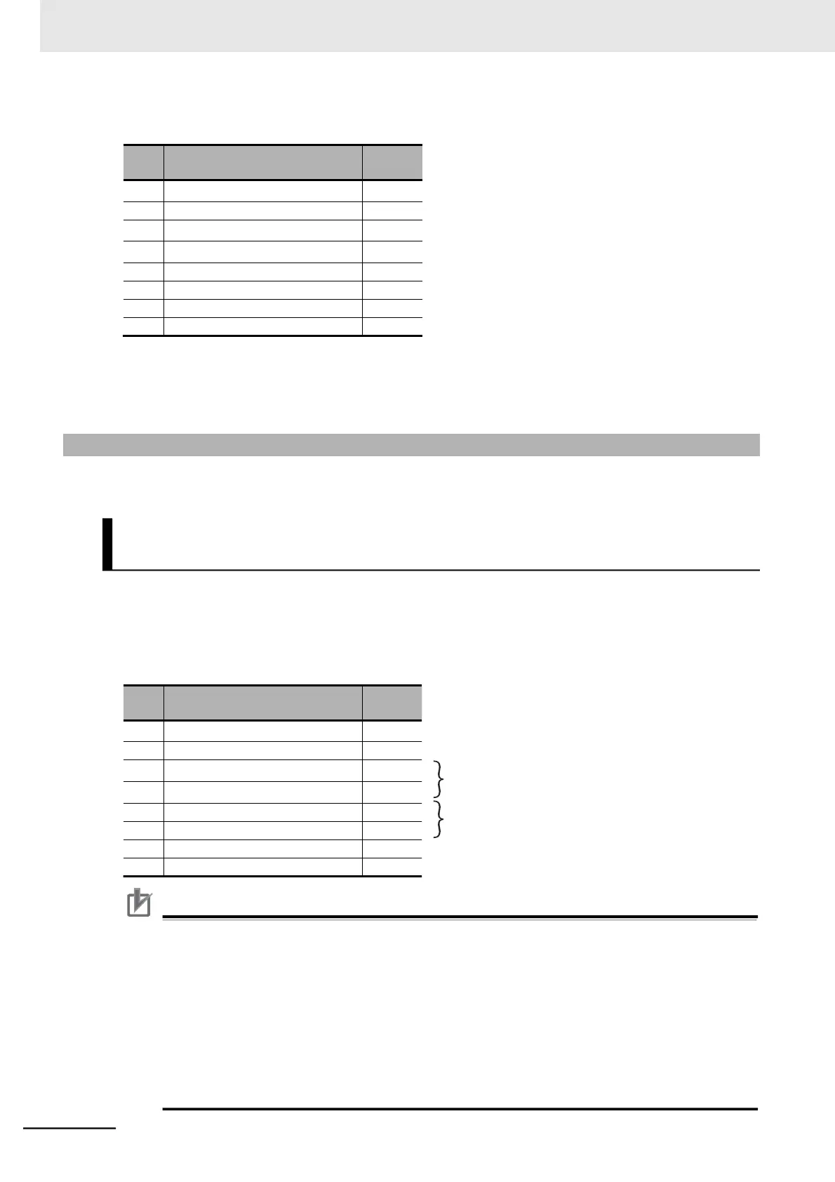
Writes data to the specified holding register.
Because the holding registers for the Output Frequency Setting/Monitor (F001) have a data resolution
of 0.01 Hz, to set 50.00 Hz, set the written data to 5000 (1388 hex).
⚫
Query
(Register address) = (Register number) − 1
1388 hex → 5000 dec → 50.00 Hz
Precautions for Correct Use
Some parameter data, such as the Output Frequency Setting/Monitor (F001), 1st/2nd Multi-step
Speed Reference 0 (A020/A220), Multi-step Speed Reference 1 to 15 (A021 to A035), 1st/2nd
Acceleration Time 1 (F002/A202), and 1st/2nd Deceleration Time 1 (F003/A203), occupy two
registers. In Modbus communication, handle these parameters as follows:
•
For reading/writing data from/to an MSB register, use the Read/Write from/to Multiple Holding
Registers function to read/write data from/to two registers at the same time.
Attempting to read/write data from/to only the MSB register results in an error and you will
receive an exception response.
•
For an LSB register, however, attempts to read/write from/to only a single register will be pro-
cessed successfully. The MSB register data remains intact in this case.