Multi-function Compact Inverter 3G3MX2-EV2 User’s Manual (I666-E1)
This terminal outputs pulses.
Output pulse: 32 kHz
max.
Output voltage: 10
VDC
Allowable current:
2 mA max.
Modbus ter-
minal
(RS-485)
RS-485 terminal
RS+: RS-485 differential (+) signal
RS−: RS-485 differential (−) signal
Speed: 115.2 kbps
max.
Built-in terminating
resistor: 120
Switching via slide
switch
Precautions for Correct Use
The Multi-function Relay Output (AL1, AL2) Function Selection (C026) is, by default, set to 05
(AL: Alarm signal).
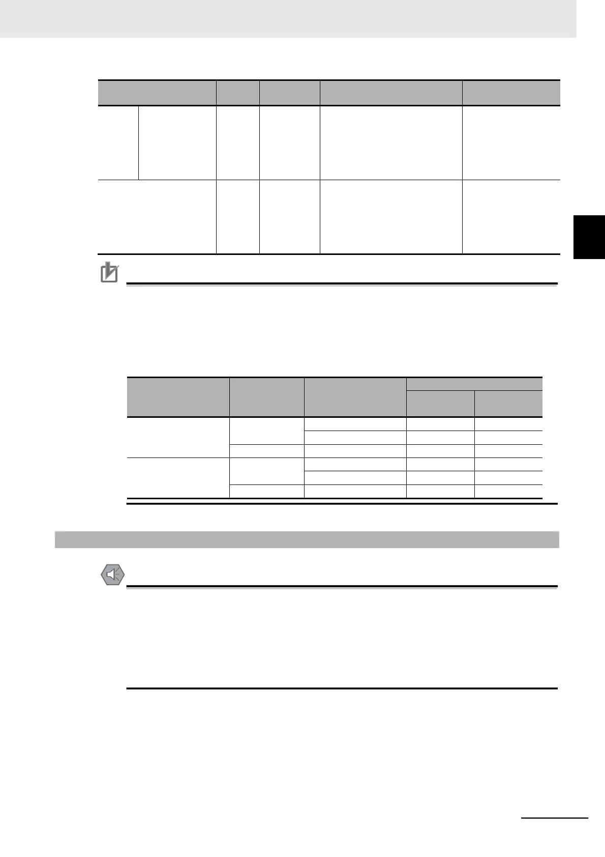
The table below shows the relationship between the relay output status when the inverter input
power supply is ON/OFF and the Multi-function Relay Output (AL1, AL2) Operation Selection
(C036) setting. Select the parameter setting appropriate to the sequence of your inverter
according to this table.
2-3-4 Wiring for Main Circuit Terminals
•
Before wiring, make sure that the charge indicator is not lit.
•
Once the power supply is turned on, the capacitor in the inverter remains charged with a high
voltage for a while after the power supply is shut off regardless of whether the inverter is run-
ning or not, which is dangerous.
•
If you change cable connections after the power supply is shut off, wait for at least
10 minutes and, before wiring, check with a circuit tester etc. to be sure that there is no resid-
ual voltage between terminals P/+ and N/−.
2-3-4 Wiring for Main Circuit Terminals