Multi-function Compact Inverter 3G3MX2-EV2 User’s Manual (I666-E1)
The diagram below shows the configuration of the inverter main circuit. The function of each peripheral
component is also described.
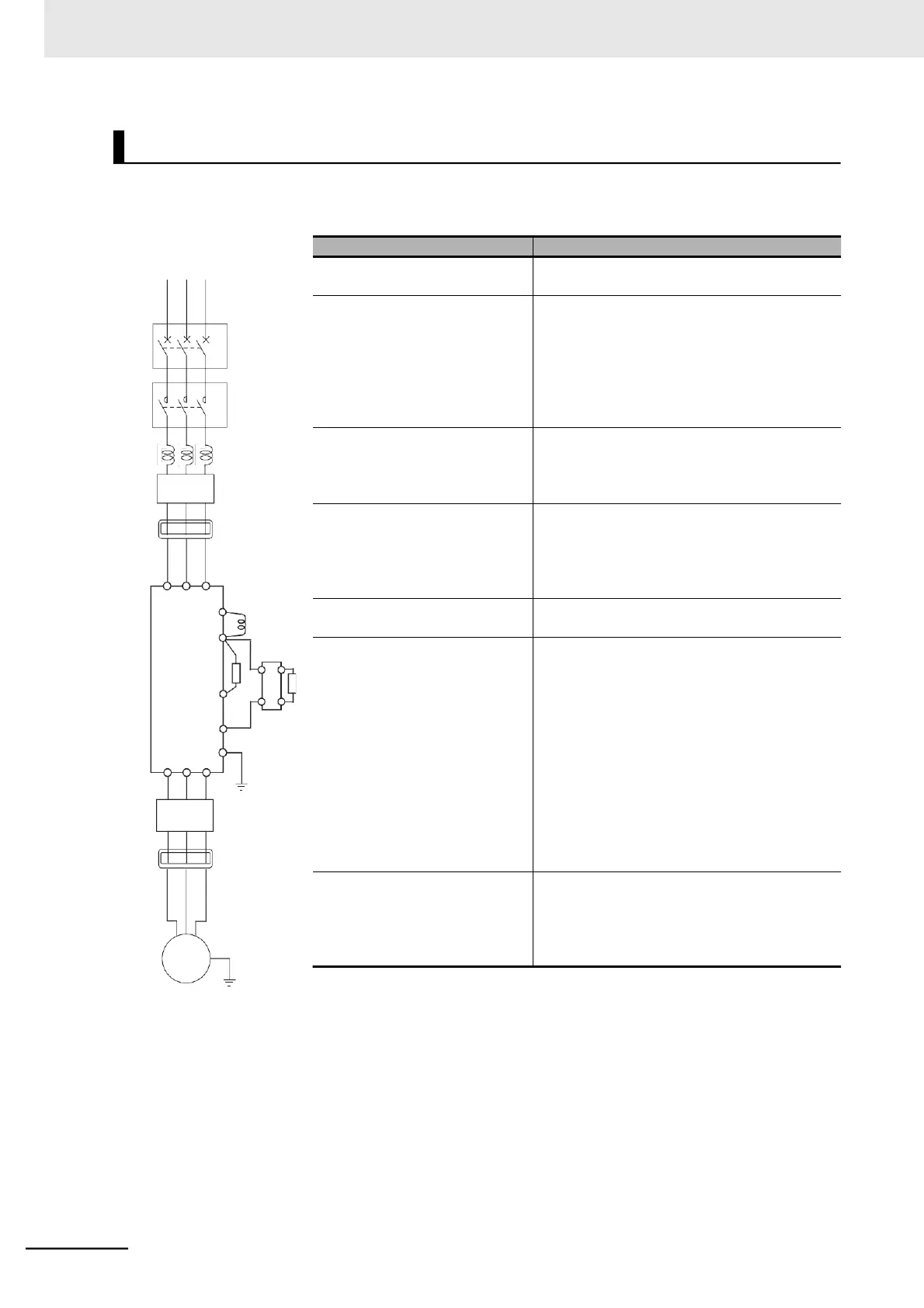
Power supply
Main Circuit Configuration Diagram
Refer to Recommended Cable Size, Wiring
Device, and Crimp Terminal on page 2-22.
This is used as a harmonic suppression mea-
sure. It also helps improve the power factor. The
AC reactor is used when the power supply volt-
age unbalance factor is 3% or more, the inverter
capacity is 500 kVA or more, or rapid change in
the power supply voltage occurs to reduce its
effect.
This filter reduces the conductive noise gener-
ated in the inverter and transmitted via wires.
Connect it to the primary side (input side) of the
inverter.
The inverter in operation may cause noise
through the power supply wiring etc., which
could affect radio receivers or other equipment
nearby. This filter reduces such noise (radiated
noise).
This reactor helps suppress harmonics gener-
ated by the inverter.
(h) Braking resistor
(i) Regenerative braking unit
These increase the amount of regenerative
energy absorption when the inverter applies
motor braking and are used to decrease the the
speed of an elevator or load with a large
moment of inertia.
All models of the 3G3MX2-EV2 Series
Inverter have built-in regenerative braking
processing circuit.
The Regenerative Braking Unit is necessary
only if a large braking torque is required and the
built-in regenerative braking processing circuit
cannot allow it.
This filter is installed between the inverter and
the motor to reduce the radiated noise emitted
from cables. It is used to reduce radio and tele-
vision interference and prevent meter and sen-
sor malfunction.