Multi-function Compact Inverter 3G3MX2-EV2 User’s Manual (I666-E1)
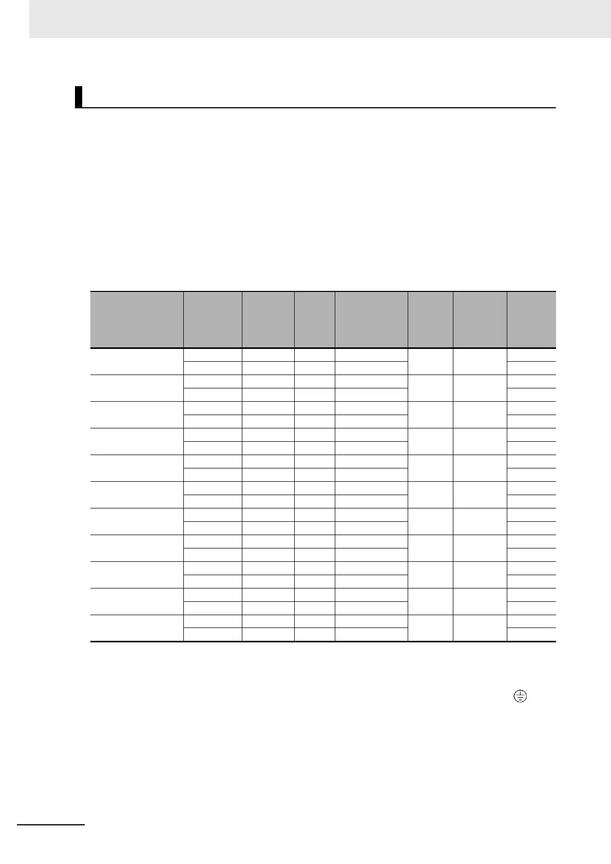
For inverter wiring, crimp terminal, and terminal screw tightening torque, refer to the table below.
•
Each table shows an example of connecting the standard 3-phase motor with four poles to an
inverter.
•
For the molded case circuit breaker (MCCB), select an appropriate product in consideration of the
breaking capacity.
•
For compliance with the UL standard requirements, be sure to perform wiring according to A-4
UL/cUL Standards Cautions on page A-9, which includes the use of UL-compliant Class-J fuses.
•
Tighten the terminal block screws with the specified torque. Weak tightening may result in a short-cir-
cuiting accident or fire. Conversely, overtightening these screws may cause damage to the terminal
block or the inverter.
⚫
3-phase 200-V Class
Maximum
applicable
motor
capacity
[kW]
Power cable,
ground cable
[mm
2
]
*1*2*3
Tightening
torque
[N·m]
*2
Molded
case
circuit
breaker
(MCCB)
*2
*1. The wire size is based on H-IV wire (with a heat resistance of 75°C).
*2. For compliance with the UL standard requirements, be sure to perform wiring according to A-4 UL/cUL Stan-
dards Cautions on page A-9.
*3. The cable is applicable to wiring to the R/L1, S/L2, T/L3, U/T1, V/T2, W/T3, +1, P/+, RB, N/-, and G ( )
terminals.
Recommended Cable Size, Wiring Device, and Crimp Terminal