6 Vector Control and Applied Functions
Multi-function Compact Inverter 3G3MX2-EV2 User’s Manual (I666-E1)
This function is enabled only when the 1st/2nd Control Method (A044/A244) is set to 03 (Sensorless
vector control).
When sensorless vector control is enabled, the inverter may output a rotation signal opposite to the
RUN command direction at low speeds, depending on the current accuracy. To prevent the motor from
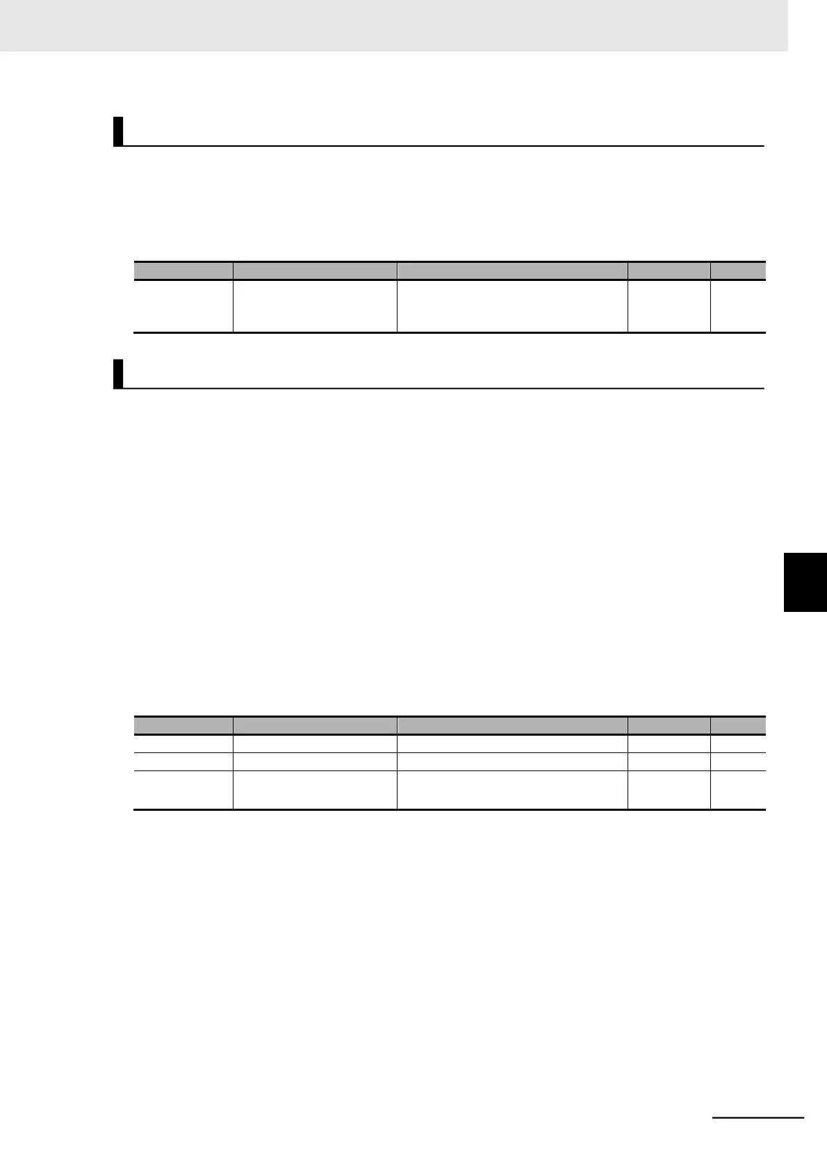
rotating in the reverse direction, set the Reverse Rotation Prevention Selection (b046) to 01 (Enabled).
Reverse Rotation
Prevention Selection
00: Disabled
01: Enabled (Motor does not rotate in
reverse.)
Use this function to monitor the motor output torque estimated by the sensorless vector control func-
tion.
This function is enabled only when the 1st/2nd Control Method (A044/A244) is set to 03 (Sensorless
vector control).
To monitor the motor output torque via the Digital Operator, display the Output Torque Monitor (d012).
For details on Output Torque Monitor, refer to 7-1-11 Output Torque Monitor [d012] on page 7-8.
For how to monitor the motor output torque via the control circuit terminal block signal, refer to 7-3-6
Terminal EO (Pulse/PWM Output) on page 7-27 or 7-3-7 Terminal AM (Analog Output) on page 7-29.
The output torque monitor function estimates the torque value equivalent to the rated current of the
inverter as 100%.
To convert it to the rated motor torque ratio, use the following formula:
Rated motor torque ratio = [Output Torque Monitor (d012) value] [Rated output current of inverter]
/ [Rated motor current]
03: Sensorless vector control
EO Selection
AM Selection
02: Output torque
11: Output torque (signed)
*1
*1. This setting is available for C028 only.
Reverse Rotation Prevention Function
6-1 Sensorless Vector Control
6-1-4 Adjustments for Sensorless Vector Control
Output Torque Monitor Function (d012)