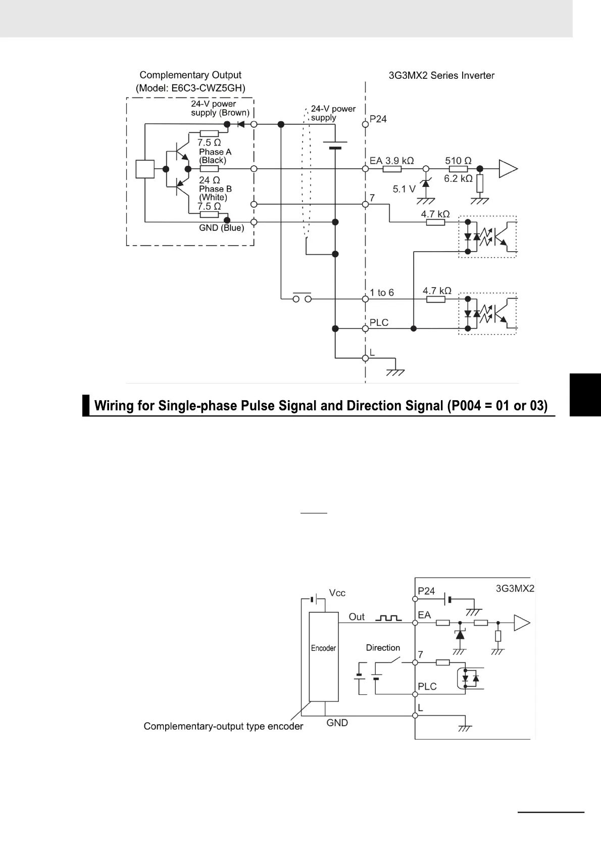
Connect the single-phase pulse signal or single-phase pulse + direction signal as shown in the diagram
below.
•
Connect the single-phase pulse signal to the pulse train input EA terminal.
•
Input the direction signal to the multi-function Input 7 terminal and set the Multi-function Input 7
Selection (C007) to 85 (EB: Rotation direction detection). Select the sink logic (NPN) or source (PNP)
by properly positioning the short-circuit bar.
•
The control circuit terminal P24 of the inverter is for a 24-V, 100-mA max. power supply. It can be
used for the encoder power supply if the consumption current for the input terminals in use and the
encoder power supply is allowable. However, this terminal must be isolated from any 24-V system
power supply for other than the encoder and inverter.