Multi-function Compact Inverter 3G3MX2-EV2 User’s Manual (I666-E1)
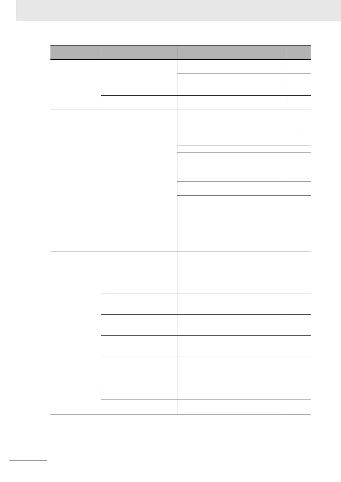
The output fre-
quency is unstable.
The parameter settings are
inappropriate.
Change the output frequency value slightly
away from the power supply frequency.
Change the 1st/2nd Stabilization Parameter
(H006/H206) value.
The load changes significantly.
Increase the motor/inverter capacity.
The power supply voltage fluc-
tuates.
Take measure to reduce the fluctuation.
The output torque is
insufficient.
The parameter settings are
inappropriate.
(During acceleration/constant
speed)
Increase the 1st/2nd Manual Torque Boost
Voltage (A042/A242), 1st/2nd Manual Torque
Boost Frequency (A043/A243) value.
Set the 1st/2nd Torque Boost Selection
(A041/A241) to 01 (Automatic torque boost).
Decrease the Carrier Frequency (b083).
Set the 1st/2nd Control Method (A044/A244)
to 03 (Sensorless vector control).
The parameter settings are
inappropriate.
(During deceleration)
Increase the value set in the 1st/2nd Deceler-
ation Time 1/2 (F003/F203/A093/A293).
Set the 1st/2nd AVR Selection (A081/A281) to
01 or 02 (OFF).
Use braking resistors or regenerative braking
units.
Removing the Digi-
tal Operator causes
the inverter to trip,
or fall in a free-run
or deceleration stop
state.
The Operation Selection at
External Operator Disconnec-
tion (b165) setting is inappro-
priate.
Set the Operation Selection at External Oper-
ator Disconnection (b165) to 02 (Ignore).
The operation/set-
ting via Modbus
communication is
not possible.
Changes are not reflected to
the communications parame-
ters.
After changing the Communication Speed
Selection (Baud Rate Selection) (C071),
Communication Parity Selection (C074), or
Communication Stop Bit Selection (C075),
cycle the power supply, or reset the inverter
(by turning ON to OFF the terminal RS).
The 1st/2nd RUN Command
Selection (A002/A202) setting
is incorrect.
Set the 1st/2nd RUN Command Selection
(A002/A202) to 03 (Modbus communication).
The 1st /2nd Frequency Refer-
ence Selection (A001/A201)
setting is incorrect.
Set the 1st /2nd Frequency Reference Selec-
tion (A001/A201) to 03 (Modbus communica-
tion).
The communications speed
setting is incorrect.
Set a correct communications speed in the
Communication Speed Selection (Baud Rate
Selection) (C071).
The unit number setting is
incorrect or overlaps.
Set a correct station number in the Communi-
cation Station No. Selection (C072).
The communications parity set-
ting is incorrect.
Set a correct parity type in the Communica-
tion Parity Selection (C074).
The communications stop bit
setting is incorrect.
Set a correct stop bit type in the Communica-
tion Stop Bit Selection (C075).
Connect the wiring correctly to the terminal
RS+/RS− on the control circuit terminal block.