Itala | INSTRUCTION MANUAL
4 GETTING STARTED
4.1 Overview
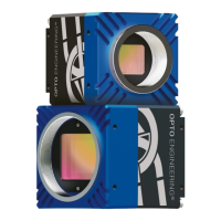
Itala is an industrial Gigabit Ethernet camera compliant with the GigE Vision and GenICam spec-
ifications. This camera is capable of transferring image data at high frame rates and over long
distances, up to hundreds of meters.
Specifically designed for harsh industrial environments, Itala cameras guarantee reliable opera-
tion and top notch performances in their class. The GigE Vision and GenICam compliance allow easy
camera integration and replacement. With flexible powering options (12-24 Vdc and Power over
Ethernet), Itala cameras are compatible with most vision systems, allowing simple and flexible
wiring configurations.
4.2 Hardware installation
4.2.1 Camera installation
The camera is provided with 4 x M3 threaded holes on each side, allowing for flexible and robust
mounting. It is recommended to mount the camera to a metal object using a metal bracket in or-
der to facilitate the heat dissipation. Before installing the camera make sure to align it correctly,
as requested by your application. Keep in mind that you can also exploit ReverseX and ReverseY
camera features to flip the image on X and Y axis directly in camera, without performance loss.
Room should be provided to ensure a good cables setting on the back of the camera.
4.2.2 Lens
Cameras which come in TYPE 1 enclosure are equipped with a standard C mount (1 inch diameter,
32 threads per inch), with a flange distance of 17.526 mm.
Cameras which come in TYPE 2 enclosure are equipped with an M42x1 threaded mount, with a
flange distance of 12 mm.
See section 5.5 for the cameras dimensional drawings.
Before installing the lens, make sure that the lens and the camera protection glass are perfectly
clean. Refer to section 3.4 for cleaning instructions.
NOTE: for heavy lenses, consider to directly mount the lens with an appropriate clamping sys-
tem instead of relying on the camera mounting holes. If the lens allows you to adjust the phase
of the mount, this operation is straightforward. Otherwise, you need to ensure that the camera
orientation will be correct after screwing it in final position.
v1.12 - eng 16