Itala | INSTRUCTION MANUAL
UserOutputValue Sets the value of the bit selected
by UserOutputSelector
IBoolean RW
UserOutputValueAll Sets the value of all the bits of
the User Output register
IInteger RW
UserOutputValueAllMask Sets the write mask to apply to
the value specified by
UserOutputValueAll before
writing it in the User Output
register
IInteger RW
Table 21: Digital I/O Control Features
6.8.1 I/O stage
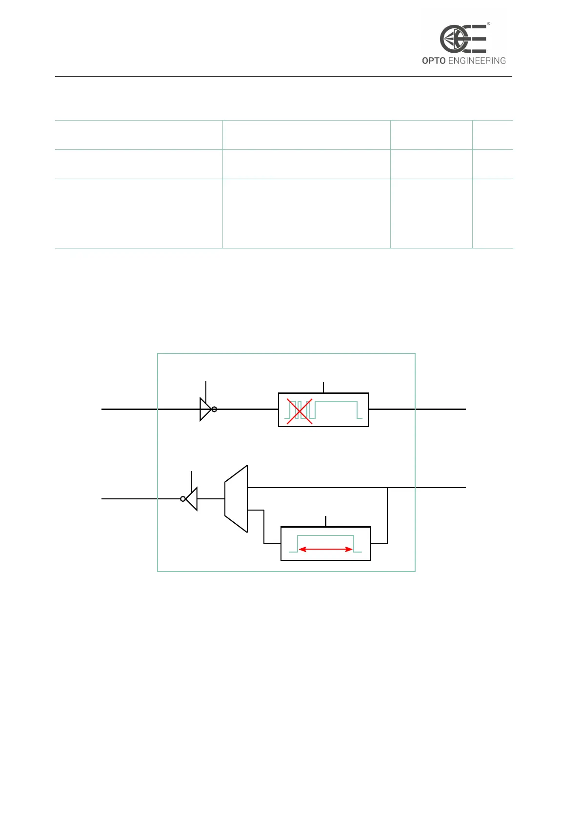
The digital I/O block includes an onboard processing stage for input trigger signals and synchro-
nization outputs.
Polarity
inversion
Debounce
stage
Pulse
generator
Polarity
inversion
adj. time
DIGITAL
INPUT
DIGITAL
OUTPUT
TO
FPGA
FROM
FPGA
Figure 66: Digital I/O stage representation.
The LineInverter feature must be activated when the input trigger works with an active-low logic,
i.e. when a falling edge must be detected. This feature applies also for synchronization outputs.
External triggers may be characterized by spurious and unwanted pulses or spikes known as bounces.
For this reason a debounce stage has been included in the processing chain.
The oeDebounceAmount feature sets a threshold level: signals whose duration is lower than
oeDebounceAmount are considered spurious pulses and therefore are discarded, while the other
ones are considered useful signal.
Obviously, the debounce stage bring intrinsically a delay in the input trigger processing, since a
v1.12 - eng 87


 To Next Page