Itala | INSTRUCTION MANUAL
A high-speed input isolator is used in the design to handle the input trigger signal with minimum
propagation delay. A TVS diode is used as countermeasure against high voltage spikes, while a
series diode prevents input polarity inversion. In addition, a current limiter circuit is also included
in order to automatically adjust the input current.
NOTE: Be careful that any damage to opto-isolated input circuitry makes it not usable anymore.
Some wiring diagram examples (both for opto-isolated and not-isolated systems) are shown in the
"Wiring connection examples" chapter (7.1).
5.7.2 Opto Isolated Output
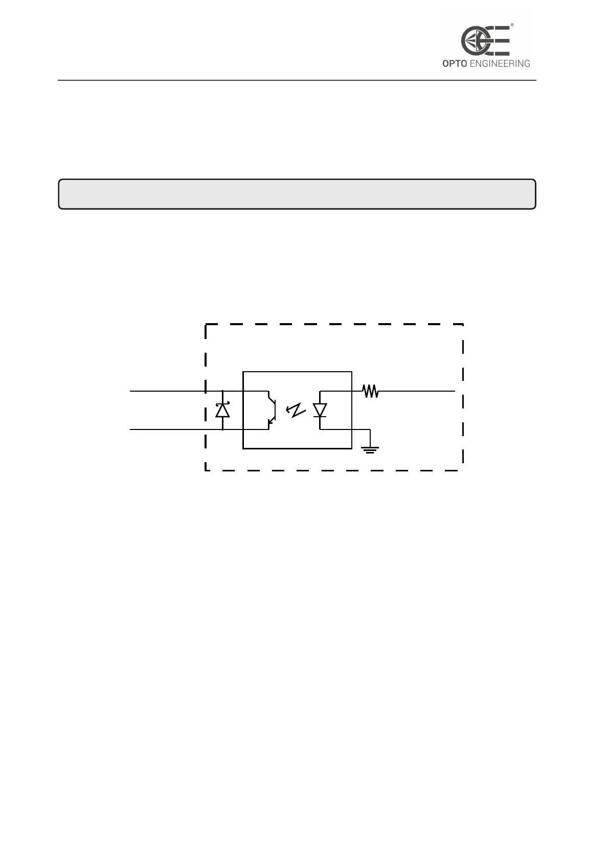
The opto-isolated output topology is schematically shown in Figure 35.
CAMERA
(OPTO-ISOLATED OUTPUT)
opto_ref_v+
opto_out
from camera
Figure 35: Opto isolated output topology.
In case of accidental connection on the output pins a bypass diode protects the transistor providing
an alternate path for the current. The reference voltage for the opto-isolated output pins can be
different from the power supply voltage, however the maximum specifications listed in Table 7
must not be exceeded.
5.8 LED and indicators
Itala is equipped with a LED indicator on the back side of the camera, next to the connectors.
This indicator shows the current status of the camera.
The color codes are listed in Table 13.
v1.12 - eng 53


 To Next Page