Itala | INSTRUCTION MANUAL
LogicBlockLUTValueAll Sets the values of all the output
bits of the selected LUT in one
access ignoring
LogicBlockLUTIndex
IInteger RW
Table 24: Logic Block Control Features
6.11.1 Logic block module
INPUT A
AND
OR
INPUT B
LUT
OUTPUT
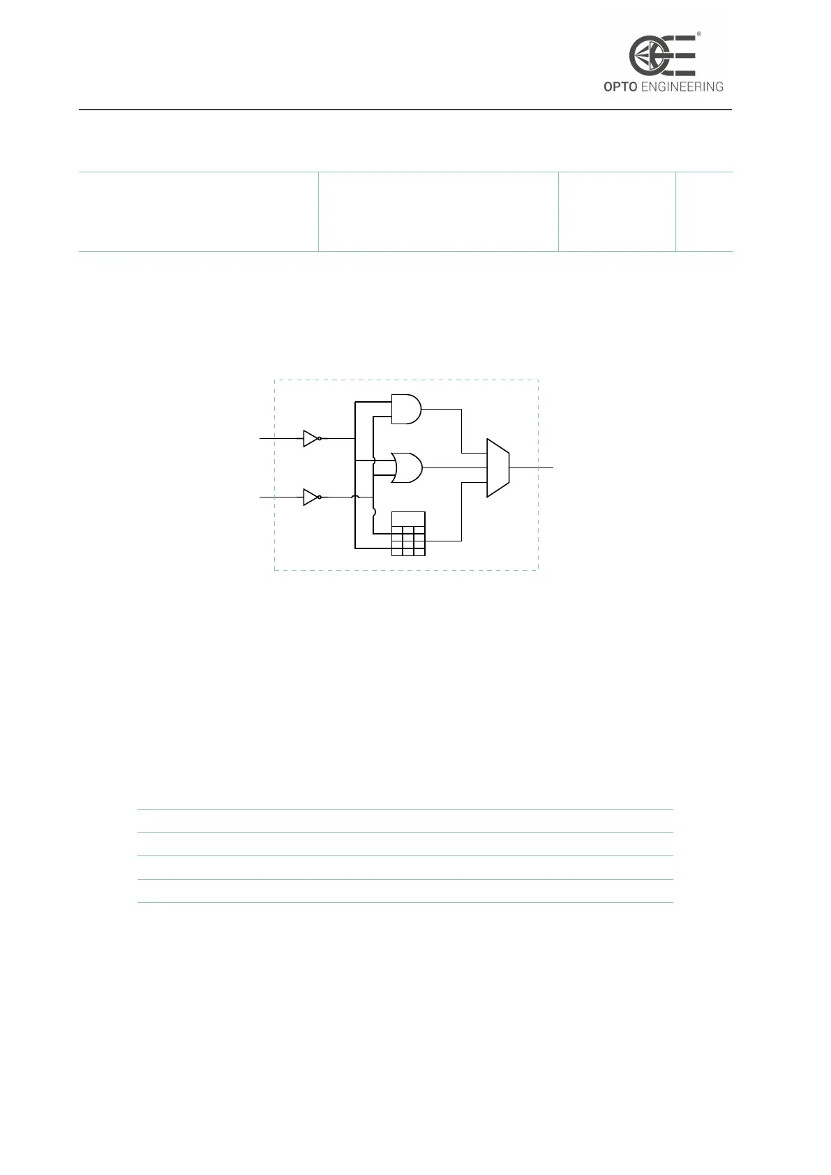
LOGIC BLOCK
Figure 70: Simplified scheme of the logic block cell.
The logic block module is mainly used to generate an output signal depending on two input con-
ditions.
This block is characterized by three different logic functions (see Fig.70):
• AND: the output of logic block is HIGH if both the inputs are HIGH;
• OR: the output of logic block is HIGH if at least one the inputs is HIGH;
• LUT: the user can freely compile the truth table of the lut:
LogicBlockLUTIndex Input A Input B LogicBlockLUTValue
0 0 0 LogicBlockLUTValue[0]
1 0 1 LogicBlockLUTValue[1]
2 1 0 LogicBlockLUTValue[2]
3 1 1 LogicBlockLUTValue[3]
Table 25: Example of LUT compilation.
In order to have the maximum flexibility, also an inverting stage has been included at the input
of this block.
v1.12 - eng 93