Itala | INSTRUCTION MANUAL
PIN Standard Liquid lens
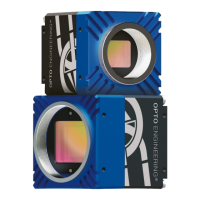
1 GND GND
2 +VIN +VIN
3 Opto OUT 3 Lens -
4 Opto IN 0 Opto IN 0
5 Opto OUT 2 Lens +
6 Opto OUT 0 Opto OUT 0
7 Opto REF GND Opto REF GND
8 RS232 RX Lens SCL
9 RS232 TX Lens SDA
10 Opto REF V+ Opto REF V+
11 Opto IN 1 Opto IN 1
12 Opto OUT 1 Lens +3.3V
Table 12: Itala pinout for both standard and liquid lens
controller version.
Figure 33: 12 pin circular connec-
tor pinout (camera front view)
5.7 I/O circuitry
All input and output pins of the I/O connector are galvanically isolated.
All the electrical specifications and the maximum voltage/current ratings are listed in Table 7 (pag.41).
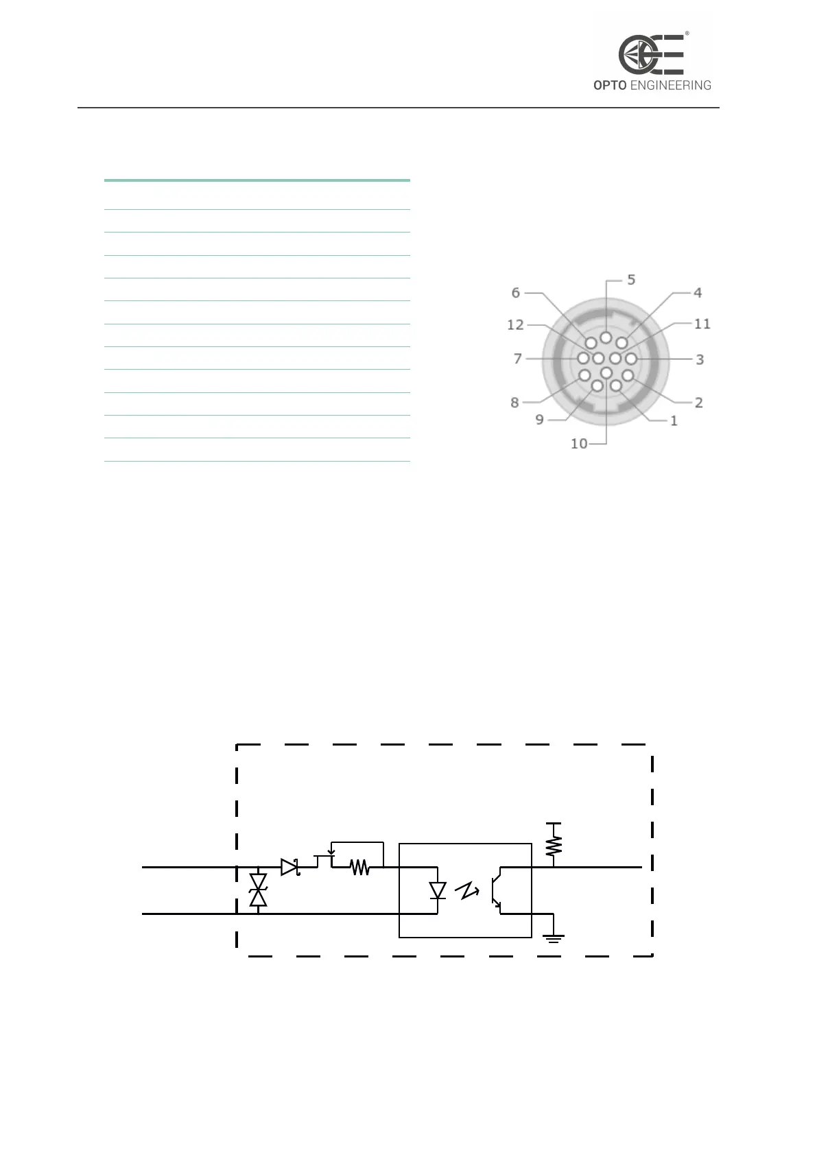
5.7.1 Opto Isolated Input
The opto-isolated input topology is schematically shown in Figure 34.
opto_ref_gnd
CAMERA
(OPTO-ISOLATED INPUT)
opto_in
to camera
+V
DD
Figure 34: Opto isolated input topology.
v1.12 - eng 52