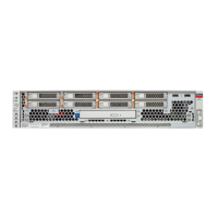
Server Block Diagram
Device NAC Name Description Device Path PCIe
Switch
Physical
Port
Device
Number
Owned By Width
/SYS/DBP/HDD3
SAS/SATA
drive in
slot 3
/pci@302/pci@2/pci@0/
pci@14/LSI,sas@0/
disk@p0
SW 1 Port 8 pci@14 CPU 1
/SYS/DBP/HDD4
SAS/SATA
drive in
slot 4
/pci@302/pci@2/pci@0/
pci@14/LSI,sas@0/
disk@p6
SW 1 Port 8 pci@14 CPU 1
/SYS/DBP/HDD5
SAS/SATA
drive in
slot 5
/pci@302/pci@2/pci@0/
pci@14/LSI,sas@0/
disk@p7
SW 1 Port 8 pci@14 CPU 1
/SYS/DBP/HDD6
SAS/SATA
drive in
slot 6
/pci@302/pci@2/pci@0/
pci@14/LSI,sas@0/
disk@p5
SW 1 Port 8 pci@14 CPU 1
/SYS/DBP/HDD7
SAS/SATA
drive in
slot 7
/pci@302/pci@2/pci@0/
pci@14/LSI,sas@0/
disk@p4
SW 1 Port 8 pci@14 CPU 1
/SYS/MB/CMP0/IOS0/RP0
CPU0
PCIe root
port 0
/pci@300/pci@1
CPU 0 x8
/SYS/MB/CMP0/IOS0/RP1
CPU0
PCIe root
port 1
/pci@300/pci@2
CPU 0 x8
/SYS/MB/CMP1/IOS0/RP0
CPU1
PCIe root
port 0
/pci@302/pci@1
CPU 1 x8
/SYS/MB/CMP1/IOS0/RP1
CPU1
PCIe root
port 1
/pci@302/pci@2
CPU 1 x8
Related Information
■
“Internal Component Locations” on page 14
■
“Server Block Diagram” on page 18
Server Block Diagram
This block diagram shows the connections between and among components and device slots on
a two CPU server. Use this block diagram to determine the optimum locations for optional cards
or other peripherals, based on your server's configuration and intended use.
18 SPARC S7-2 Server Service Manual • March 2017
 Loading...
