Helix Ottobock | 39
Alignment control and optimisation of the prosthesis under load should be done using the 743L100 L.A.S.A.R.
Posture.
1
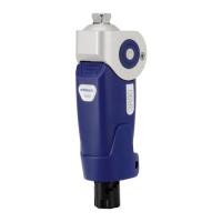
Adapt the alignment by only adjusting the plantar exion.
2
The load line should run approx. 30 mm anterior to the pivot point of the knee joint.
The prosthesis side should be sufciently loaded (> 35% of the body weight). The following values can be
used to check the alignment: The load line should run approx. 50 mm anterior to the ankle adapter screw
(dependent on the type and size of the prosthetic foot) as well as approx. 0 to ±10 mm through the pelvic
socket reference line.
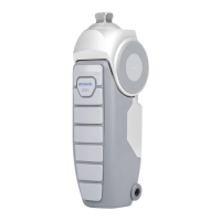
After completion of the alignment, reassemble the upper section cap of the Helix
3D
Hip Joint.
3.6 Dynamic trial tting
INFORMATION
Please make sure you are thoroughly familiar with the adjustment possibilities and their effects! Only then you
will be able to optimally adjust the prosthesis to the requirements of the prosthesis wearer.
INFORMATION
For use of the C-Leg: Always also observe the C-Leg knee joint Instructions for Use (647H215) and the C-Soft
Instructions for Use (647G268) before adjusting the gait parameters on the Helix
3D
hip joint.
For use of the Genium: Always also observe the Genium knee joint Instructions for Use (647G573) and the
description of use of the X-Soft contained therein before adjusting the gait parameters on the Helix
3D
hip joint.
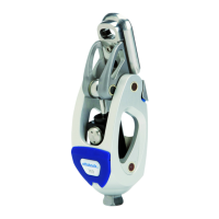
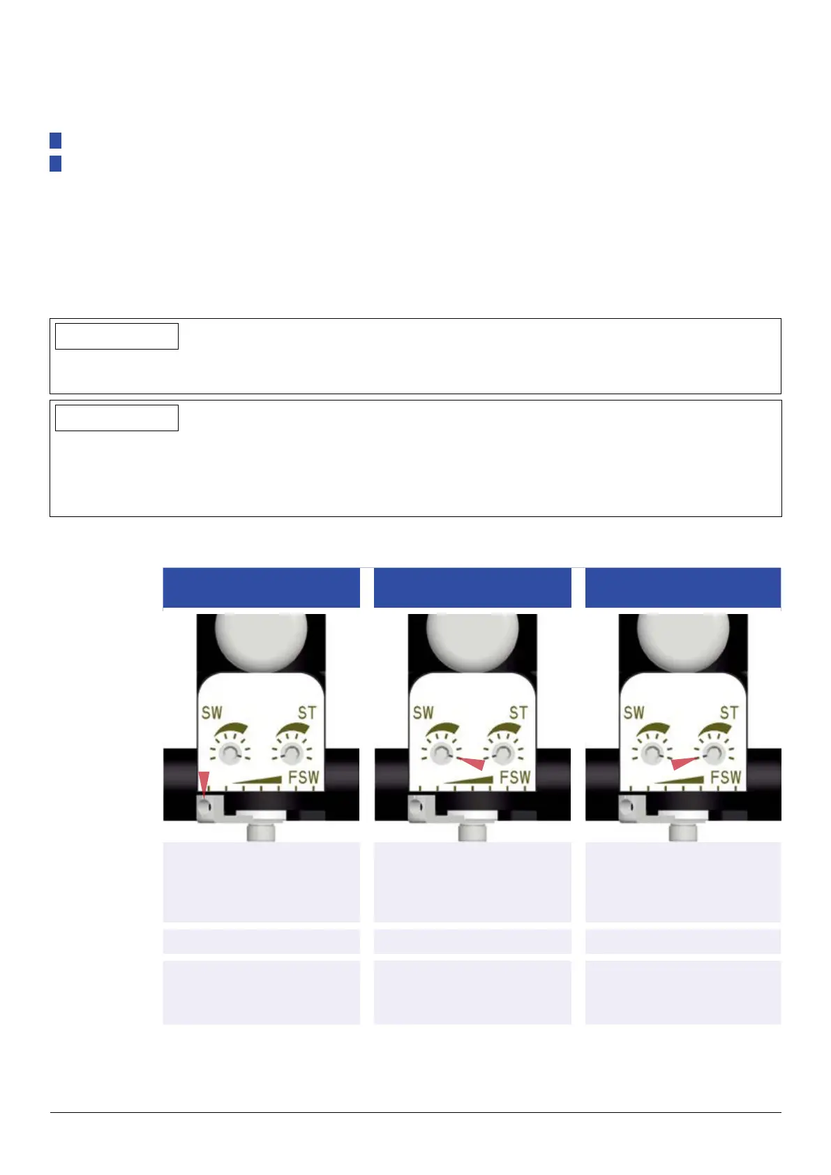
3.6.1 Explanation of the adjustment possibilities
Free swing range
(FSW)
Swing phase resistance
(SW)
Stance phase resistance
(ST)
Parameter
The hip joint allows to set a
certain stride length within
which it exes freely i. e. with-
out resistance.
The free swing range is fol-
lowed by a signicant increase
in resistance to limit the stride.
The stance phase resistance
allows comfortable extension
of the prosthesis.
Factory setting
Low High Low
Adjustment feature
Lower adjustment lever is set
to left position.
Left adjustment screw of the
hydraulic unit is fully turned to
the right.
Right adjustment screw of the
hydraulic unit is fully turned to
the left.
 Loading...