42 | Ottobock Helix
INFORMATION
Stance phase resistance is a new aspect in the prosthetic tting after amputations in the pelvic area. Therefore,
please make the adjustment very carefully and permanently check whether the resistance can be increased
further! It is important for the prosthesis wearer that he can put weight on the prosthesis as long as possible
during the stance phase.
The stance phase on the moving hip joint is possible because of the high resistance and should be considered
the goal of the walking training, even if the prosthesis wearer might feel uncomfortable in the beginning. Please
take the time to understand this important procedure and to explain and practice the procedure with the pros-
thesis wearer. Only then the prosthesis wearer will be able to fully benet from the advantages of this product.
3.7 Finishing the prosthesis
The 3S27=L/R44 Foam Cover can be used for nishing the pelvic socket prosthesis. Allow a 60 mm "compres-
sion allowance" to minimise the protective foam cover’s effect on knee function. When determining the proper
cover length, increase the linear thigh dimension by 30 mm and the linear shin dimension by the same amount.
Use 710D4 Torque Wrench to nish the prosthesis and secure all set screws with 636K13 Loctite. Please observe
the following torques:
Screws Torque
501F9=* Flat headed screws on the lamination plate
(with Torx socket)
25 Nm (Wrench/Bit TX 40)
Small cap screw of lamination adapter 2 Nm
Set screws of rotation adapter 4R57 10 Nm / Torque above the rotation adapter
All other set screws 15 Nm
Finally, verify once again that all adjustments are optimal by having the prosthesis wearer walk with the nished
prosthesis. If necessary, readjust the prosthesis to compensate for inuences by the foam cover.
3.8 Maintenance
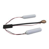
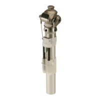
Replacing the expansion springs
To support the swing phase (exion), the joint contains tension springs on the left and right (order no.: 4G430,
red). These springs store energy during extension of the Helix
3D
Hip Joint in the stance phase and return the energy
at the beginning of exion. This results in signicantly faster initiation of hip exion and larger ground clearance
during the swing phase. Two additional normal tension springs (order no.: 4G430, red) and two stronger tension
springs (order no.: 4G430=2, grey) are included.
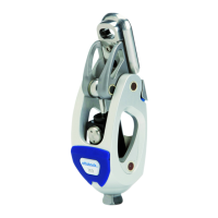
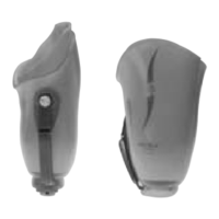
Worn or defective expansion springs can be replaced as follows:
1. First open the front cap.
2. Then replace the defective expansion springs with new ones.
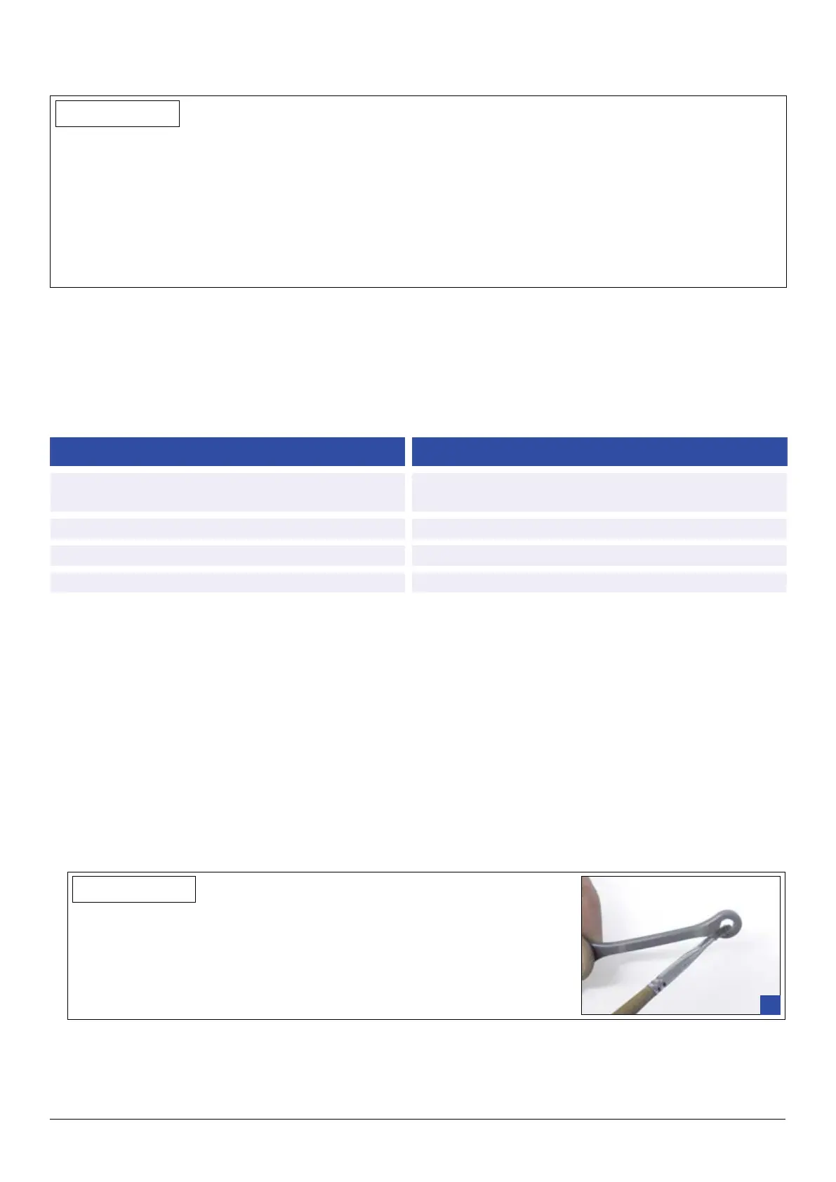
INFORMATION
To remove the expansion springs, use a slotted screwdriver without sharp
edges!
Before installing the 4G430 or 4G430=2 expansion springs, the eyelets of
the expansion spring must be greased throughly with 633F30 special grease
(Fig. 1).
1
3. Close the cap and insert the attachment pins in the lower section.
 Loading...