9.1 PWM Output Function
9-7
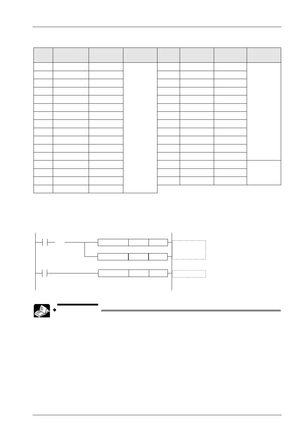
Control code
S
Frequency
Cycle (ms) Resolution S
Frequency
Cycle
Resolution
K0 1.5 666.67
1000
K16 2000.0 0.50
1000
K1 2.0 500.00 K17 3000.0 0.33
K2
4.0 250.00
K18
6000.0 0.17
K3
6.0 166.67
K19
12500.0 0.08
K4
8.0 125.00
K20
15000.0 0.067
K5
10.0 100.00
K21
20000.0 0.050
K6 20.0 50.00 K22 25000.0 0.040
K7 50.0 20.00 K23 30000.0 0.033
K8
100.0 10.00
K24
40000.0 0.025
K9
200.0 5.00
K25
50000.0 0.020
K10
400.0 2.50
K26
60000.0 0.017
K11
K27
K12 700.0 1.48 K28 80000.0 0.0125
100
K13 1000.0 1.00 K29 90000.0 0.0111
K14
1300.0 0.77
K30
100000.0 0.010
K15
1600.0 0.625
Example of program
The following sample shows the program for performing the PWM output with 1kHz and the
duty ratio of 50% from CH0 (Y0).
CH No.0 PWM
FPΣ PWM
K13: f=1KHz
T=1ms
K500:50.0%
R0
K13F0 MV DT0
R1
DT0F173 PWMH K0
( )
DF
K500F0 MV DT1
• For details of the allocations of I/O and flags, refer to "12.2.3 When Using
PWM Output Function".
• For details of the FPΣ mode, refer to "11. FPΣ Mode".
 Loading...


