10.3 High-speed Counter Instruction
10-9
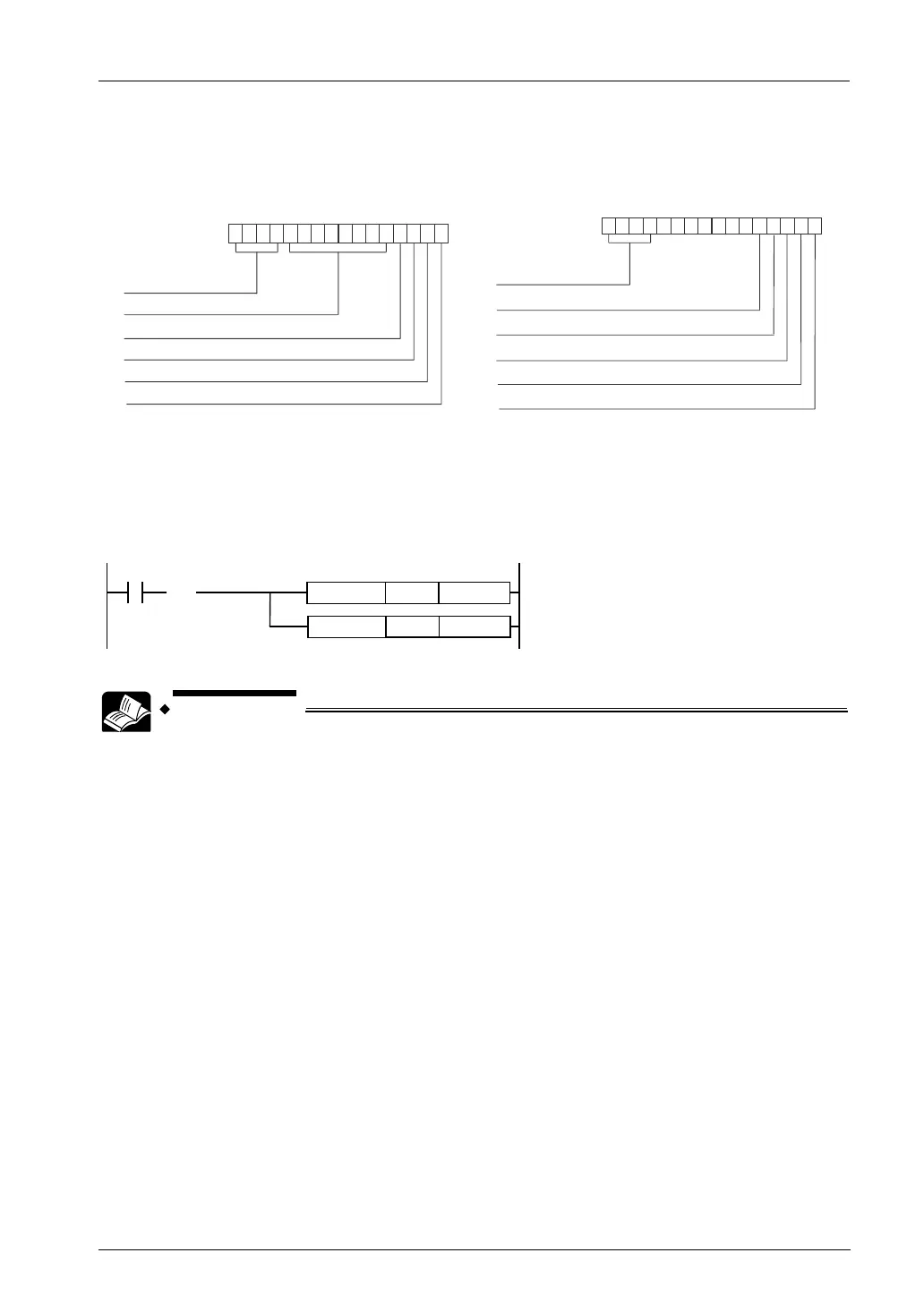
Allocation of control codes
• The following bits are allocated according to the specified channel and functions.
FP0H mode
FP
mode
bit no.
15
0
Software reset
0 0 0 0 0 0 0 0
8 7
0: Disable 1: Enable
H00: Fixed
Count
0: Enable 1: Disable
External reset input
0: Valid 1: Invalid
High-speed counter
instruction
0: Continue 1: Cancel
Channel specification
H0 to H3: CH0 to CH3
bit no.
15 43210
Near home input
Reset input setting
0: Valid, 1: Invalid
High-speed counter instruction clear
pulse output stop
0: Continue, 1: Clear, stop
Channel specification
H0 to H3: CH0 to CH3
Software reset
0: Disable, 1: Enable
Count
0: Enable 1: Disable
0: Invalid, 1:Valid
• When controlling the above functions using external inputs, arbitrary inputs can be allocated.
Example of program
The following example shows the program for performing the software reset of the high-speed
counter CH0 using the input X7.
X7
DT90052H1
F0 MV
DT90052H0
F0 MV
( )
DF
• For details of the allocations of I/O and flags, refer to "12.2.4 When Using
High-speed Counter Function".
• For details of the FPΣ mode, refer to "11. FPΣ Mode".