272
Setting Inspection Conditions
6.
Set “Output Signal Guarantee Time”.
Settable range is 1 - 1000 ms. (Default: 10 ms)
When Handshaking is not employed:
OUT signal is output in the doubled cycle of the time specified in this item.
When Handshaking is employed:
After handshaking of the first inspection, output of the second inspection is not executed during
"Output Signal Guarantee Time".
7.
Set "Timeout (ms)" when you employ handshake.
Settable range is 4 - 2000 ms. (Default: 5000 ms)
Specify maximum time from data output to ACKNOWLEDGE signal (data receipt completion signal) input
from the external device. If ACKNOWLEDGE signal is not input within this period, a time error occurs and
ERROR0 signal is output.
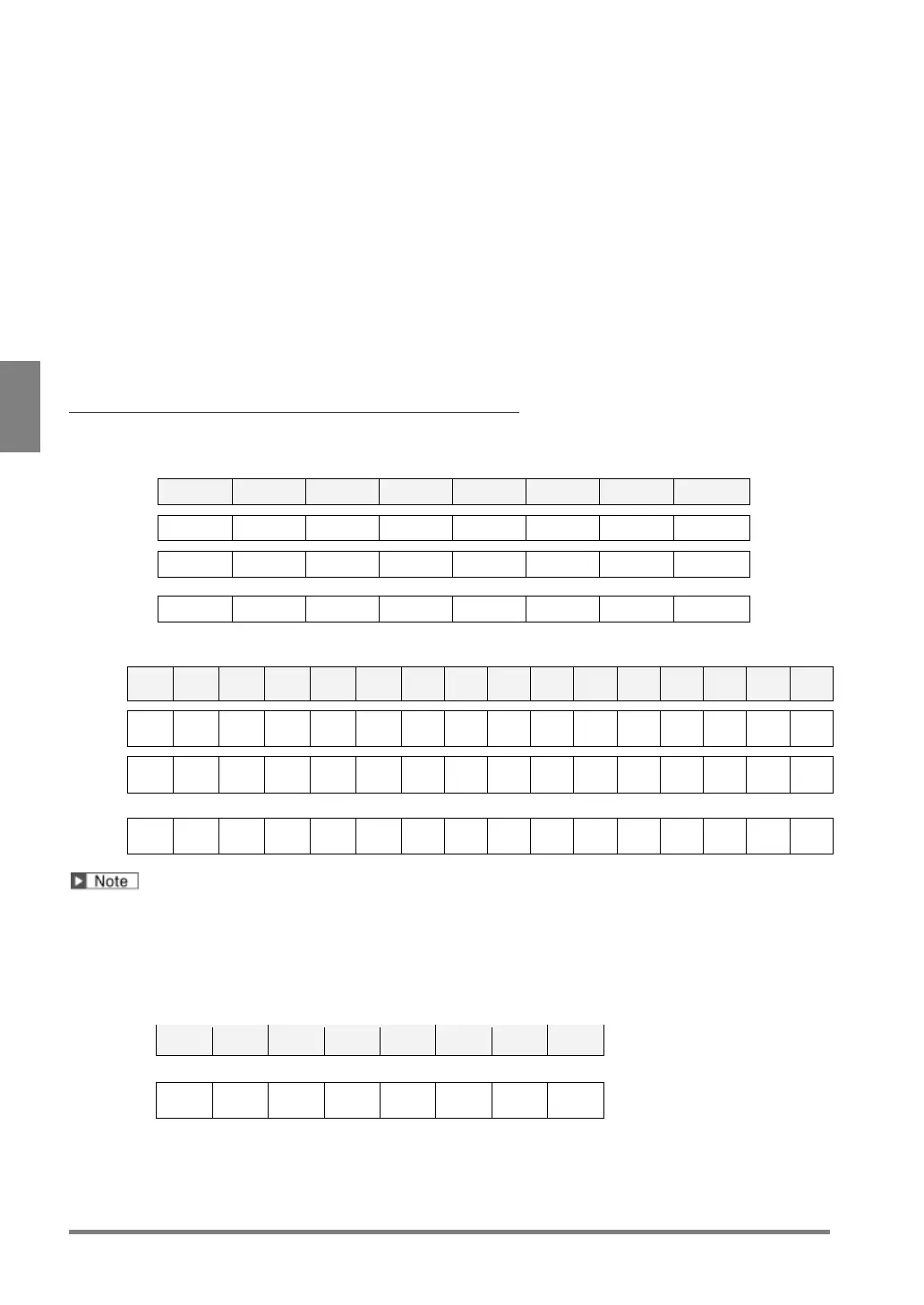
Output Example when outputting only Judgement
Output Data Assignment in the case of “8 bit” (1000-data output)
OUT7 OUT6 OUT5 OUT4 OUT3 OUT2 OUT1 OUT0
1st JDC007 JDC006 JDC005 JDC004 JDC003 JDC002 JDC001 JDC000
2nd JDC015 JDC014 JDC013 JDC012 JDC011 JDC010 JDC009 JDC008
125th JDC999 JDC998 JDC997 JDC996 JDC995 JDC994 JDC993 JDC992
Output Data Assignment in the case of “16 bit” (1000-data output)
1st
2nd
:
63rd OFF OFF OFF OFF OFF OFF OFF OFF
Until the last number of data which has been set a judgement expression, data will be output. For example,
when No.0-5 and No.30 are set, No.0-30 are output and after No.30 is not output. No.6-29 are output “OFF”.
In the case of Execution Mode = Automatic Switch
(When the lastly executed block = Block No.3, Bit Width [8 bit])
OUT7 OUT6 OUT5 OUT4 OUT3 OUT2 OUT1 OUT0
1st: Judgement result of Block No.3
Afterwards, outputs to the last number of judgement expression created
*Only the results of the block executed lastly are output.
 Loading...