325
Setting of Operation and RUN Menu
4.
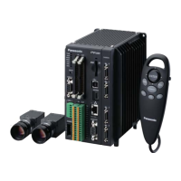
Select “Display” or “Hide” for "Area".
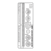
Area is an inspection area frame of each checker.
In the right figure, it is indicated with a dotted line.
5.
Select “Display” or “Hide” for "Scan Direction".
This item is available only when selecting "Display" for
"Area".
"Scan Direction" is an arrow to indicate the scan
direction of a checker.
In the right figure, it is indicated at the right edge of
the upper side.
Target Checker
Binary Edge / Gray Edge / Connector (Gray Edge) /
Smart Edge (Circle) / Smart Edge (Line)
(including Position Adjustment and Area Size
Adjustment)
6.
Select “Display” or “Hide” for "Detect Position".
Detect Position is a line or mark indicating a position
detected by each checker.
In the right figure, it is indicated with a solid line.
The detect position in the right figure is the line and
mark at the edge of the circle.
7.
Select “All” or “Display NG checkers only”. for “Display Condition”.
Display NG Checkers Only:
Displays the area and detect position of checkers judged as NG.
(Only when selecting "Display" for each item.)
All (Default):
Displays the areas and detect positions of all checkers (only when selecting "Display") regardless of
an inspection result.
The "Display Condition" can be set only for the inspection area, scan direction and detected position of a
checker.
8.
Select “Display” or “Hide” for "Geometry Calculation", "Character/Figure Drawing" and "Marker"
respectively.
9.
Select “No” or “Yes” for “Calibration Scale”.
[No] (Default): Not display a calibration scale.
[Yes]: Displays a calibration scale.
 Loading...