3-32 Installing the Drive 590 Series DC Digital Drive
598/599 Power Board (AH385128U009)
External stack drives from 720A upwards
The power supplies for the controller are generated from the single phase auxiliary supply via the control transformer. A bridge rectifier and filter
capacitor feed an unregulated 40V dc supply to a high-efficiency switched mode pre-regulator. This generates 24V dc which is used for thyristor stack
firing, digital I/O and other power functions. The logic supply is stabilised to +5V using a high-efficiency switched mode regulator. Stabilised ±15V
supplies are generated for the analog hardware. All power supplies are short circuit protected, and the 40V and 5V supplies are protected against over
voltage using a crowbar protection. The control transformer is provided with two primary taps which allow auxiliary supply voltages of 110V ac and
240V ac. The auxiliary supply fuse FS3 on the power supply PCB protects the control transformer primary. This fuse is also cleared should the
crowbar operate, which can happen if the wrong auxiliary supply voltage tap is selected. Fuses FS1 and FS2 protect the cooling fan, and also the main
contactor on 110/120V boards and the pilot relay on 220/240V boards.
This board is suitable for either 110-240V or 220-240V and is altered by a simple transformer tap change.
Heatsink Cooling Fan Connections
When fitted, these fans are connected on the power board to FAN LIVE (F27), FAN NEUTRAL (F24) and FAN COMMON (F23) as described below:
• A single fan should be matched to the auxiliary supply and connected to F27 and F24.
• Two fans using a 110/115V auxiliary supply should be connected in parallel to F27 and F24.
• Two fans using a 220/240V auxiliary supply should be connected in series to F27 and F24 using F23 as the centre point.
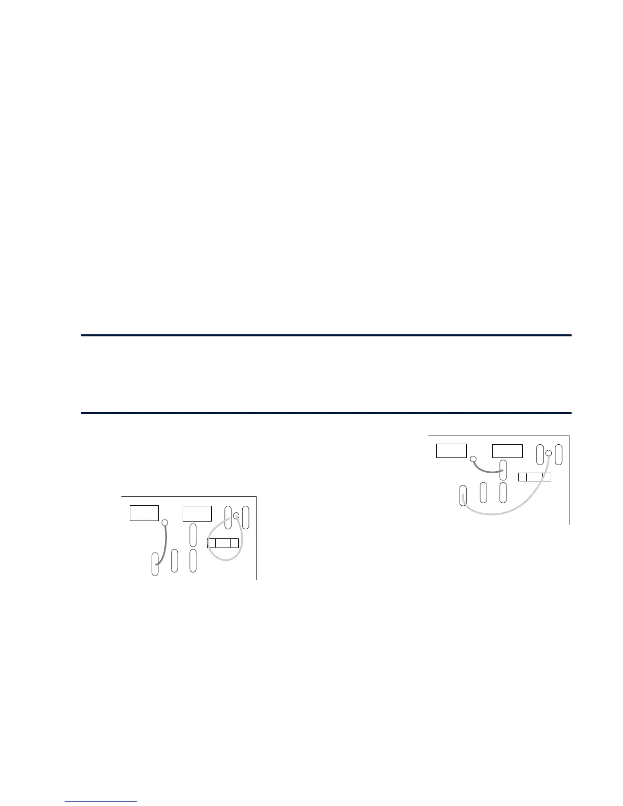
Contactor Supply
The controller requires an ac or dc power contactor in series with the main power path to ensure
correct power-up sequencing. This contactor is directly initiated by the Microcontroller via an
isolating relay which drives the contactor coil with the same voltage as that of the auxiliary supply.
This is achieved by the brown wire connection from COIL LIVE (F28) to RELAY (F25) and the
blue wire connection from COIL NEUTRAL (F21) to CONTACTOR RETURN (F26).
However, if an alternative supply for the contactor coil is required move the brown wire from F25 to
F22 , and move the blue wire from F21 to F25. The external coil supply can now be switched using a
volt-free contact between terminals D5 and D6.
F25
F23
F24
F21
FS1
F22
F27
D5 D6
D7 D8
F26
F28
F25
F23
F24
F21
FS1
F22
F27
D5 D6
D7 D8
F26
F28