EasyManuals Logo

Parker 591C User Manual

Parker 591C
401 pages
To Next Page IconTo Next Page
To Previous Page IconTo Previous Page
Page #21 background imageLoading...
Page #21 background image
2-4 Product Overview 590 Series DC Digital Drive
Component Identification
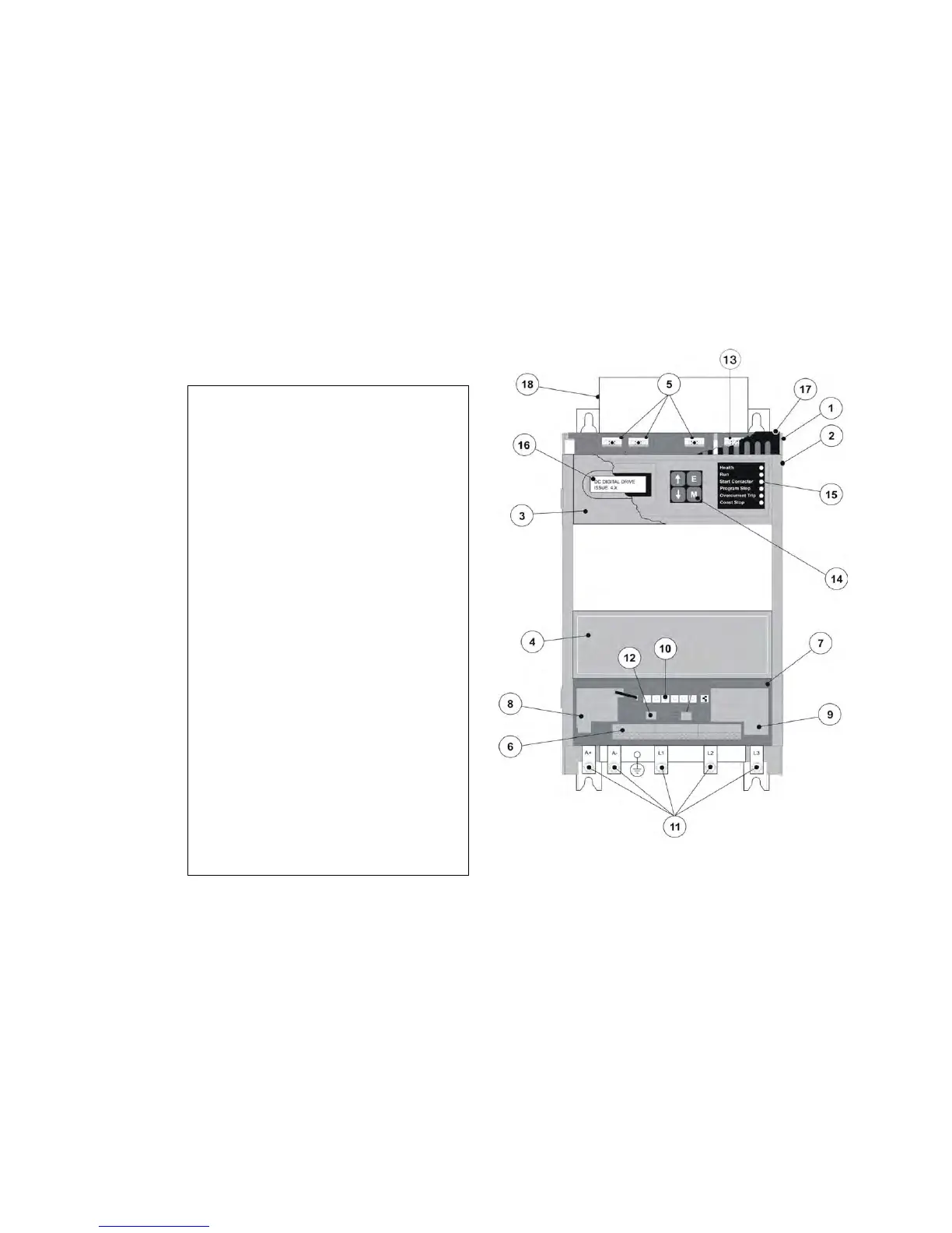
Figure 2-1 View of Component Parts (110A model illustrated)
1 Main converter assembly
2 Converter door assembly
3 Hinged MMI cover
4 Hinged terminal cover
5 Field wiring terminals
6 Control terminals
7 Control board
8 Tacho/Encoder/Microtach option board
9 Main Serial Port COMMS option module (P1)
10 Calibration panel
11 Busbars - main power input and output
12 System Port (P3)
13 Auxiliary Supply Terminal
14 Man-Machine Interface (MMI) keypad
15 Status LEDs
16 MMI display
17 IP20 Top Cover
18 IP20 Fan Housing (where fitted)

Table of Contents

Questions and Answers:

Question and Answer IconNeed help?

Do you have a question about the Parker 591C and is the answer not in the manual?

Parker 591C Specifications

General IconGeneral
Control ModesTorque, Position
FeedbackEncoder
CommunicationRS-485
Operating Temperature0°C to 55°C
Protection FeaturesOvercurrent, Overvoltage, Overtemperature

Related product manuals