3-36 Installing the Drive 590 Series DC Digital Drive
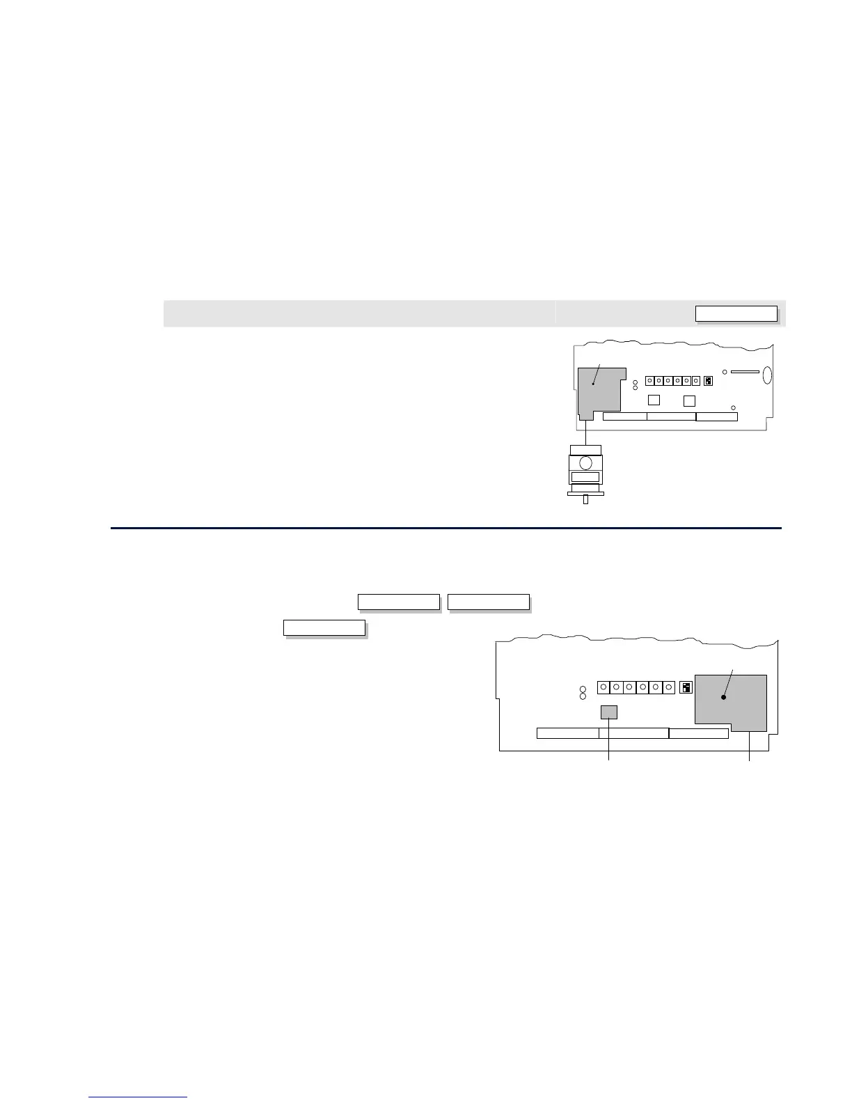
Combined Tacho and Encoder Feedback
ENCODER/ANALOG
If an analog tachogenerator and digital encoder are to be used, the Encoder Option Board
receives the digital signal, the analog signal is routed to Terminals B2 (Tacho) and B1 (0V).
Please refer to Parker SSD Drives Engineering Department for assistance with this feature.
ENCODER OPTION
BOARD
Board
Control
Digital Encoder/Analog Tachogenera
ANALOG
DIGITAL
Communications Option Boards
Comms Option Board (P1)
Two protocols are supported, each requiring a different board:
• EI BYSINCH (EI BINARY or EI ASCII)
EI BINARY
EI ASCII
• PROFIBUS (OPTION)
OPTION
The board allows the 590 to be controlled as part of a system. The system can
also comprise other Parker SSD Drives products such as the 605 and 584SV
Inverters, or any other equipment using the same protocol.
NOTE The 5721 Operator Station is not supported by this product.
Board
Control
BOARD
COMMS OPTION
System Port
(P3)
Main Serial Por