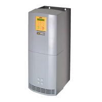
890SD Standalone Drive
Page 5-50 890CS Common Bus Supply - Frames B & D; 890CD Common Bus Drive and 890SD Standalone Drive - Frames B, C & D
8
9
10
11
B
C
D
1
2
3
4
5
6
7
E
Routine 2: Remote Mode
This routine assumes that the drive’s control terminals are wired as shown in "Control Connection
Diagram" on page 5-
20.
IMPORTANT Ensure that the speed potentiometer is set to zero.
On the 890SD Standalone Drive:
1. The drive should be "healthy" now it is powered-up: no flashing trip messages displayed, and the 6901
keypad's HEALTH LED is lit (the RUN LED remains off).
If the drive has tripped, the keypad will be flashing a trip message, and the 6901 keypad's HEALTH
LED will flash. Refer to Chapter 10: “Trips and Fault Finding” to investigate and remove the cause of
the trip.
2. Select Remote Mode - refer to Chapter 8: "The Keypad" for details, or power-down and power up the
unit to re-initialise in Remote mode.
3. To Start in Remote Mode, close the "Run" switch on your control panel (applying 24V to DIN2,
terminal X15/02 - RUN).
4. Turn the speed potentiometer up a little to apply a small speed setpoint (applying a variable voltage to
AIN3, terminal X12/04 - REMOTE SETPOINT). The 6901 keypad's RUN LED will light and the motor
will rotate slowly (the RUN LED will flash if the setpoint is at zero). The 6511 keypad will display a
rotating symbol.
Reverse the motor’s direction of rotation either by pressing the FORWARD/REVERSE key on the 6901
keypad, or by swapping two of the motor phases (WARNING: Disconnect the mains supply first).
5. To Stop in Remote Mode, open the "Run" switch on your control panel (removing 24V from DIN2,
terminal X15/02 - RUN).

 Loading...


