68
2 t
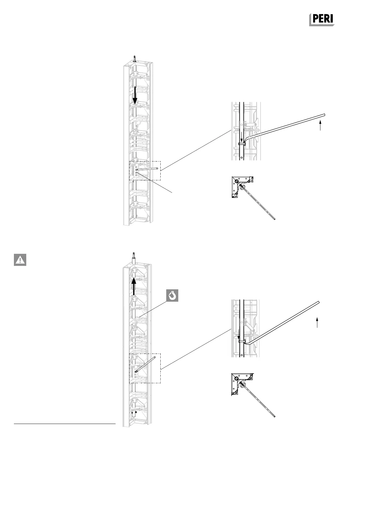
Shuttering
1. Insert crowbar into the opening (89.4)
and press upwards.
J The tube slides downwards.
(Fig. A17.04 + A17.04a + A17.04b)
2. Press movable edge strut outwards
using the crowbar.
J The transition from shaft corner to
following panel is flush and tight.
Striking
– Perm. load capacity of 2 t per
load-bearing point.
– Do not exceed the crane capacity.
– Follow Instructions for Use for
Lifting Gear Combi MX.
1. Remove tie rods of the closing
formwork
1)
2. Attach crane lifting gear to the
load-bearing point (Fig. A17.05):
– with 4 shaft corners, use 4
load-bearing points,
– with 2 shaft corners, use 2
load-bearing points.
3. Tension crane slings.
4. Press crowbar downwards.
J The tube slides upwards and the
striking position has been adjusted.
(Fig. A17.05 + A17.05a + A17.05b)
5. Pull the complete internal formwork
upwards and move.
1) Closing formwork is the external formwork
of the shaft.
Fig. A17.05a
Fig. A17.05
Fig. A17.05b
Fig. A17.0 4a
Fig. A17.0 4
A17 Shaft formwork
TRIO Panel Formwork
Instructions for Assembly and Use – Standard Configuration
Fig. A17.0 4b
89.4
AuV TRIO EX.indb 68 11.10.17 09:51