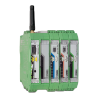
RAD-900-...
100/138
PHOENIX CONTACT 3827_en_B
9.4.1 Assigning I/O extension modules to the register
Use the white thumbwheel on the I/O extension module to assign an I/O-MAP address in the
Modbus memory map. Example: If you set the thumbwheel of an input module to the
I/O-MAP address = 01, the register assignment is 30010.
Table 9-5 Setting the white thumbwheel for register 30010 (read)
9.5 Modbus memory map
The I/O data from the extension modules is stored in an internal register, the Modbus mem-
ory map. In PLC/Modbus RTU mode, the Modbus memory map is contained in the master
wireless module with the RAD ID = 01. In PLC/Modbus RTU dual mode, the Modbus mem-
ory map is contained within each wireless module. The data contained can be read or writ-
ten by a Modbus master.
The following process data tables for the individual extension modules show at what posi-
tion the I/O data is stored in the Modbus memory map. You can find a complete overview of
the Modbus memory map from page 109 onwards.
The RSSI signal register can be found starting on page 113.
Read
register
I/O-MAP address
(white thumbwheel)
Consecutive
number 0 ... 9
30 01 0

 Loading...