Installation
3827_en_B PHOENIX CONTACT 59/138
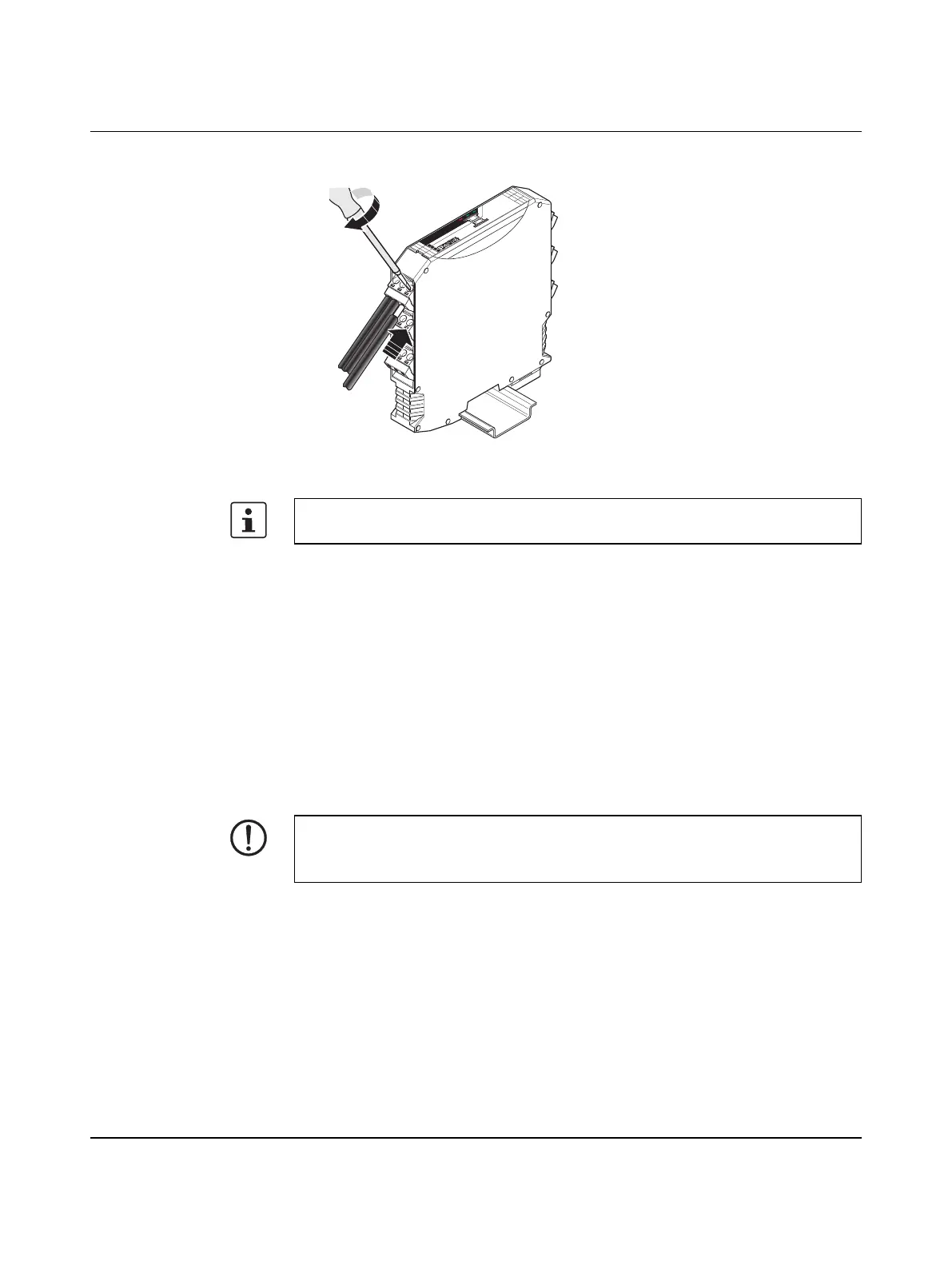
4.1.2 Connecting wires
Figure 4-3 Connecting wires
1. Crimp ferrules to the wires. Permissible cable cross section: 0.2 mm
2
... 2.5 mm
2
(24 … 14 AWG).
2. Insert the wire with ferrule into the corresponding connection terminal block.
3. Use a screwdriver to tighten the screw in the opening above the connection terminal
block. Tightening torque: 0.6 Nm
4.1.3 Connecting the power supply
Via screw terminal blocks
Connect a DC voltage source (10.8 V ... 30.5 V DC) to the wireless module. The nominal
voltage is 24 V DC. Supply voltage to the device via the terminals 1.1 (24 V) and 1.2 (0 V).
In the case of a connection station, it is sufficient to supply the first device in the group.
For easy installation, it is also possible to pull out the screw terminal block from the device
and to re-insert it after having connected the wires.
A
B
8
8
PWR
DAT
ERR
NOTE:
The power supply must be connected to terminals 1.1 and 1.2. Power supply via the DIN
rail connector (TBUS) is not permitted.

 Loading...