RAD-900-...
18/138
PHOENIX CONTACT 3827_en_B
3.1.4 Diagnostic LEDs
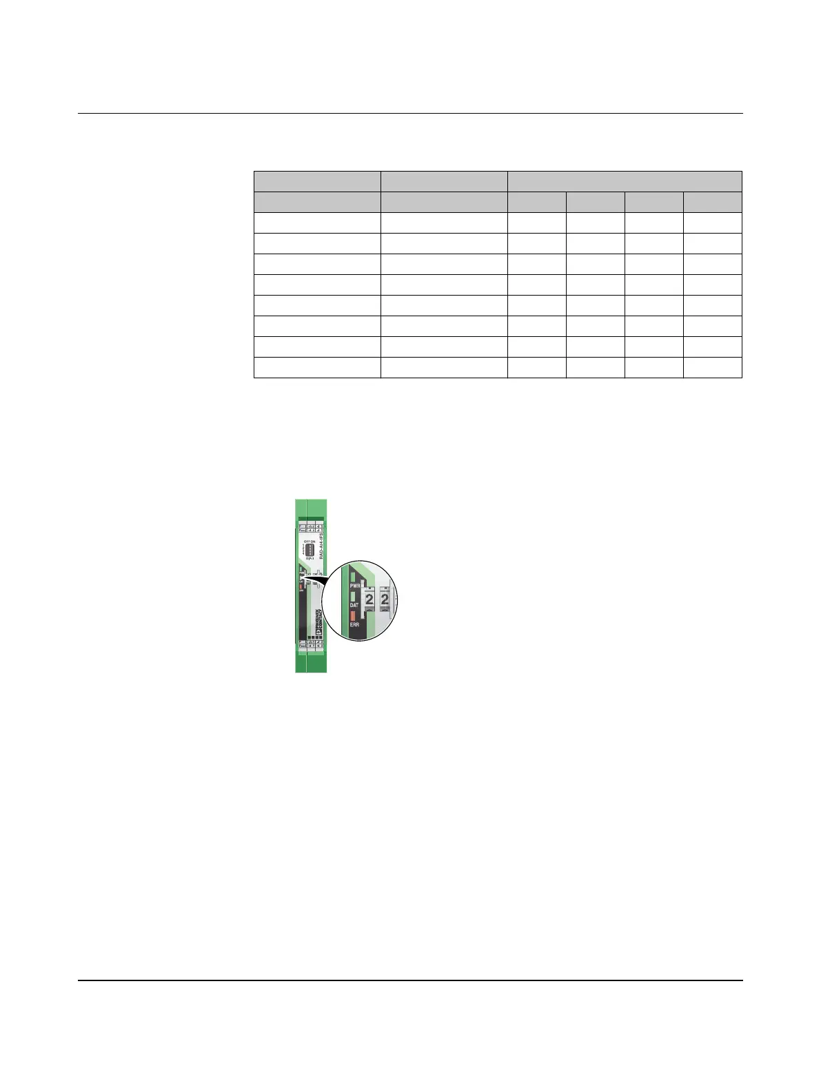
The RAD-AI4-IFS I/O extension module uses a total of three LEDs to indicate the operating
states.
Figure 3-4 Diagnostic LEDs of the RAD-AI4-IFS
PWR LED
The green PWR LED indicates the supply voltage status.
DAT LED
The green DAT LED indicates the bus communication status.
Table 3-2 DIP switches of the RAD-AI4-IFS
DIP switch
Setting Input signal 1 2 3 4
Analog IN1 0 mA ... 20 mA OFF
Analog IN1 4 mA ... 20 mA ON
Analog IN2 0 mA ... 20 mA OFF
Analog IN2 4 mA ... 20 mA ON
Analog IN3 0 mA ... 20 mA OFF
Analog IN3 4 mA ... 20 mA ON
Analog IN4 0 mA ... 20 mA OFF
Analog IN4 4 mA ... 20 mA ON
OFF No supply voltage
ON Supply voltage OK
OFF No communication
Flashing Configuration and addressing mode
ON Cyclic data communication
-I4+I4PWR4
-I3+I3PWR3
-I2+I2PWR2
-I1+I1PWR1
OFF ON
DIP-1
1
2
3
4
PWR
DAT
ERR
44
3WR3
22
1WR1

 Loading...