RAD-900-...
38/138
PHOENIX CONTACT 3827_en_B
Reset counter state by setting the inputs
• Set the corresponding input for at least 0.5 seconds:
– Set the DI3 input in order to reset the DI1 counter state.
– Set the DI5 input in order to reset the DI7 counter state.
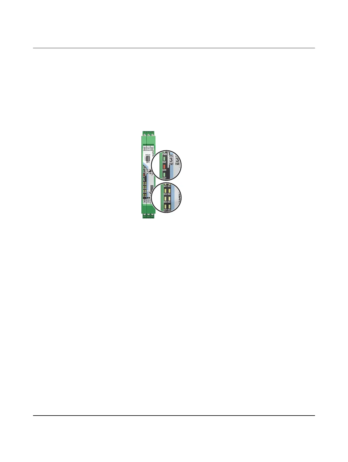
3.5.5 Diagnostic LEDs
The RAD-DI8-IFS I/O extension module uses a total of twelve LEDs to indicate the operating
states.
Figure 3-27 Diagnostic LEDs of the RAD-DI8-IFS
PWR LED
The green PWR LED indicates the supply voltage status.
DAT LED
The green DAT LED indicates the bus communication status.
ERR LED
The red ERR LED indicates the error status.
OFF No supply voltage
ON Supply voltage OK
OFF No communication
Flashing Configuration and addressing mode
ON Cyclic data communication
OFF No error
Flashing
Slow (1.4 Hz) I/O-MAP address changed or mode switched using DIP
switch 1, but not yet applied
Fast (2.8 Hz) No bus communication
ON Critical internal error

 Loading...