RAD-900-...
30/138
PHOENIX CONTACT 3827_en_B
3.3.4 Diagnostic LEDs
The RAD-AO4-IFS I/O extension module uses a total of three LEDs to indicate the operating
states.
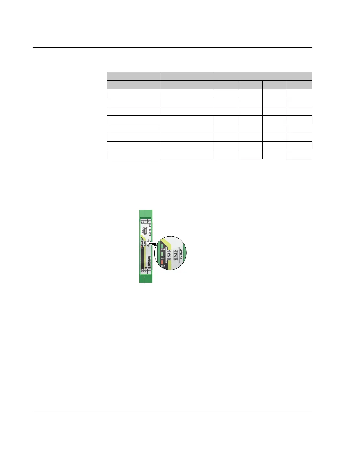
Figure 3-20 Diagnostic LEDs of the RAD-AO4-IFS
PWR LED
The green PWR LED indicates the supply voltage status.
DAT LED
The green DAT LED indicates the bus communication status.
Table 3-5 DIP switches of the RAD-AO4-IFS
DIP switch
Input Output signal 1 2 3 4
Analog OUT1 RESET OFF
Analog OUT1 HOLD ON
Analog OUT2 RESET OFF
Analog OUT2 HOLD ON
Analog OUT3 RESET OFF
Analog OUT3 HOLD ON
Analog OUT4 RESET OFF
Analog OUT4 HOLD ON
OFF No supply voltage
ON Supply voltage OK
OFF No communication
Flashing Configuration and addressing mode
ON Cyclic data communication
3
4U4
U3
I4
I3
1
2U2
U1
I2
I1
OFF ON
DIP-1
1
2
3
4
PWR
DAT
ERR
444
3
3
222
11

 Loading...