RAD-900-...
82/138
PHOENIX CONTACT 3827_en_B
– The input and output data is saved in a Modbus memory map in the wireless module.
You can read or write the process data via the serial interface of the master wireless
module (RAD ID = 01) using the Modbus RTU command. The process data tables can
be found starting at “Modbus memory map” on page 100.
5.8 Starting up the RAD-900-DAIO6
5.8.1 Setting the address of the RAD-900-DAIO6 via the thumb-
wheel
For an I/O-to-I/O transmission of signals, both the RAD ID and I/O-MAP address are set
using the yellow thumbwheel on the RAD-900-DAIO6.
Addressing extension modules
• Use the thumbwheel to set the address.
• Press the SET button on the front of the wireless module to read the current
configuration.
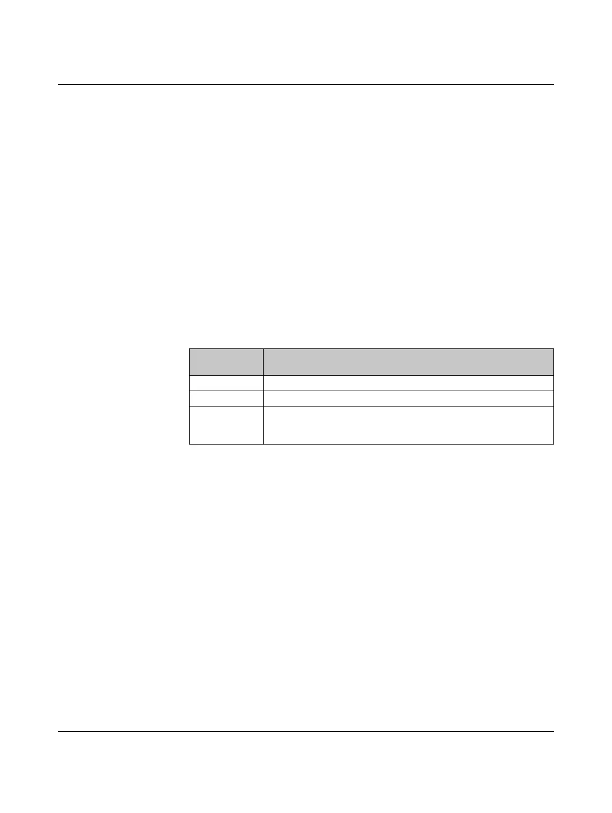
The following settings can be made using the yellow thumbwheel:
The following conditions must be met:
– Assign a maximum of 1 ... 99 addresses to the RAD-900-DAIO6 in the entire wireless
network. If the address is set to 01, the RAD-900-DAIO6 may only be used in point-to-
point mode with another RAD-900-DAIO6.
Wireless module in I/O data mode
The RAD-900-DAIO6 may be used to create a point-to-point or point-to-multipoint
connection with RAD-900-IFS devices. In this case, set the I/O-MAP address to between 02
and 99 using the white thumbwheel on the corresponding RAD-DAIO6-IFS extension
module(s) to match the yellow thumbwheel setting on the RAD-900-DAIO6.
– The I/O-MAP address of an input module may only appear once in the network.
– The input channels are directly assigned to the corresponding output channels at the
other wireless station.
Thumbwheel
setting
Description
01 ... 99 RAD ID and I/O-MAP address
01 Delivery state
**,
1* ... 9*,
*1 … *9
Settings not permitted

 Loading...