Description of I/O extension modules
3827_en_B PHOENIX CONTACT 49/138
3.7.5 Setting the I/O-MAP address
Use the thumbwheel to set the I/O-MAP address. The extension module in the Radioline
wireless system is addressed using the I/O-MAP address. You can assign a maximum of
01 ... 99 addresses to the I/O extension modules in the entire wireless network.
3.7.6 Process data in PLC/Modbus RTU mode
The process image of the I/O extension module consists of four data words. For additional
information, please refer to Section 3.7, “RAD-DO8-IFS - digital extension module with eight
outputs”.
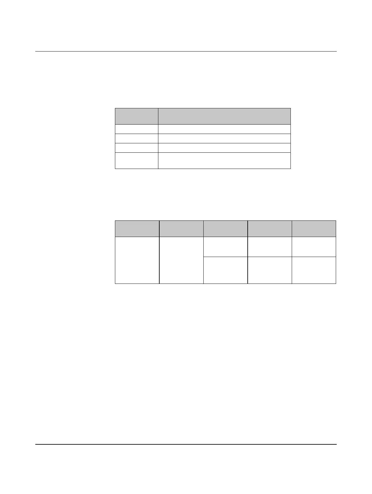
Table 3-13 Setting the I/O-MAP address for the RAD-DO8-IFS
Thumbwheel
setting
Description
01 ... 99 I/O-MAP address
00 Delivery state
**, 1* ... 9* Setting not permitted
*1 ... *9 Interface System slave address, for use with other
Interface System (IFS) master devices
I/O module Module type
ID
Number of
registers
Address area Function code
RAD-DO8-IFS 11
hex
02
hex
Outputs
40xx0 ... 40xx1 fc 03.16
02
hex
Short-circuit
detection
30xx0 ... 30xx1 fc 04

 Loading...