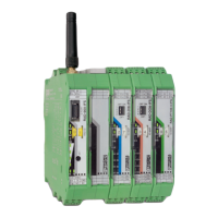
RAD-900-...
48/138
PHOENIX CONTACT 3827_en_B
PWR LED
The green PWR LED indicates the supply voltage status.
DAT LED
The green DAT LED indicates the bus communication status.
ERR LED
The red ERR LED indicates the error status, e.g., if a corresponding input module has not
been found.
DO1 ... DO8
The yellow DO1 ... DO8 LEDs indicate the status of the digital outputs.
OFF No supply voltage
ON Supply voltage OK
OFF No communication
Flashing Configuration and addressing mode
ON Cyclic data communication
OFF No error
Flashing Wireless module in I/O data mode
– Missing input module
– No bus communication
Wireless module in PLC/Modbus RTU mode
– No Modbus communication (safe state of outputs, depending on
DIP switch setting)
– Short circuit at one output or several outputs
ON Critical internal error
DO1 ... DO4 Flashing Short circuit at one output or several outputs 1 ... 4
DO5 ... DO8 Flashing Short circuit at one output or several outputs 5 ... 8

 Loading...