RAD-900-...
34/138
PHOENIX CONTACT 3827_en_B
ERR LED
The red ERR LED indicates the error status, e.g., if a corresponding output module has not
been found.
DI1 ... DI4
The yellow DI1 ... DI4 LEDs indicate the status of the digital inputs.
3.4.4 Setting the I/O-MAP address
Use the thumbwheel to set the I/O-MAP address. The extension module in the Radioline
wireless system is addressed using the I/O-MAP address. You can assign a maximum of
01 ... 99 addresses to the I/O extension modules in the entire wireless network.
3.4.5 Process data in PLC/Modbus RTU mode
The process image of the I/O extension module consists of two data words. For additional
information, please refer to Section 3.4, “RAD-DI4-IFS - digital extension module with four
inputs”.
OFF No error
Flashing
Slow (1.4 Hz) I/O-MAP address changed
Fast (2.8 Hz) No bus communication
ON Critical internal error
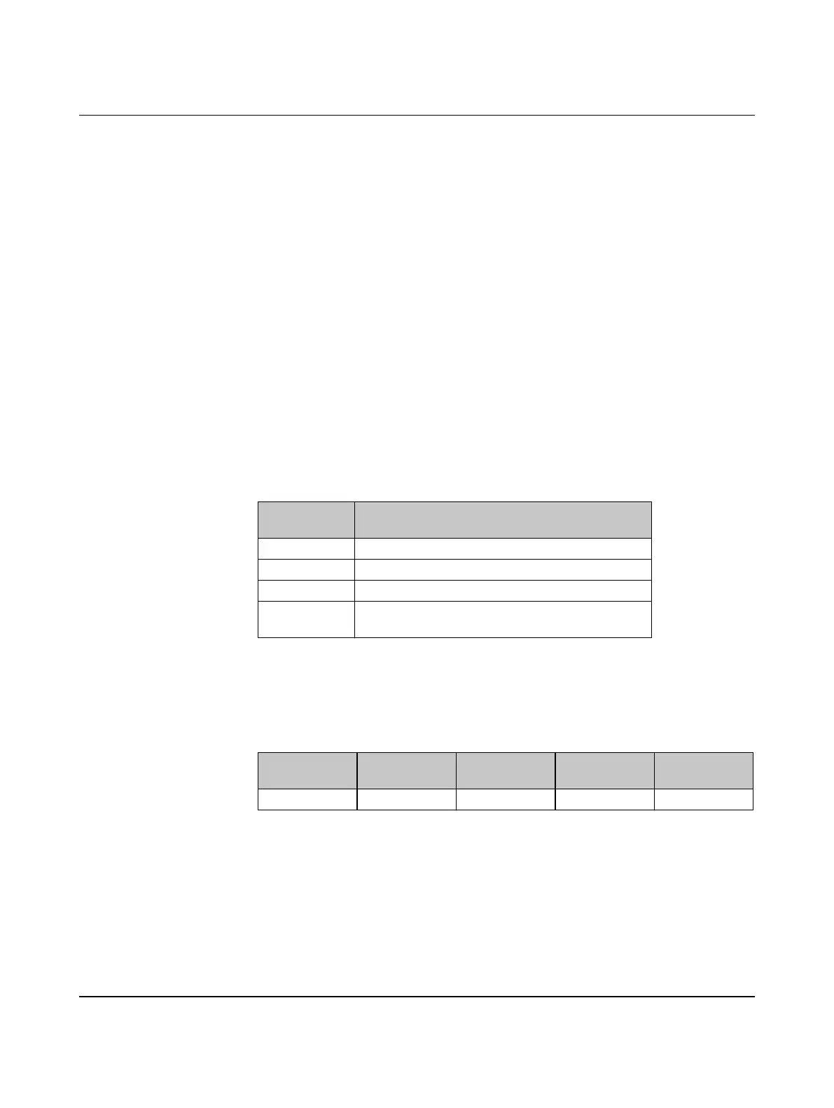
Table 3-7 Setting the I/O-MAP address for the RAD-DI4-IFS
Thumbwheel
setting
Description
01 ... 99 I/O-MAP address
00 Delivery state
**, 1* ... 9* Setting not permitted
*1 ... *9 Interface System slave address, for use with other
Interface System (IFS) master devices
I/O module Module type
ID
Number of
registers
Address area Function code
RAD-DI4-IFS 01
hex
02
hex
30xx0 ... 30xx1 fc 04

 Loading...