Installation
3827_en_B PHOENIX CONTACT 65/138
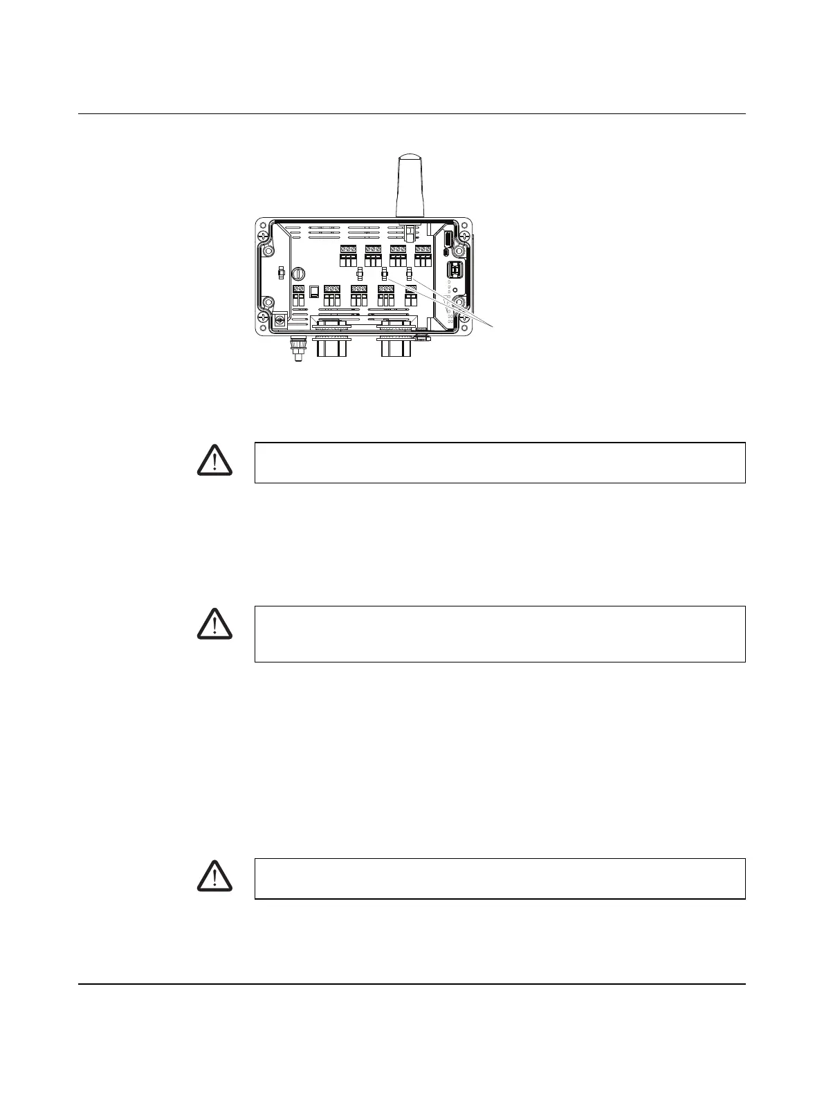
4. Install zip ties to manage wire routing.
Figure 4-13 Zip ties
4.2.4 Connecting power
Select the input voltage range via the selector switch
• When the switch is set to DC mode, connect a DC voltage source (10.8 … 30.5 V DC)
to the wireless module. The nominal voltage is 24 V DC.
• When the switch is set to AC mode, connect an AC voltage source (100 … 240 V AC)
to the wireless module. When powered by an AC voltage source, the maximum
temperature is 65°C.
In order to prevent damage to the wireless module, Phoenix Contact recommends the
installation of a surge arrester. Wiring between the surge arrester and the wireless module
should be as short as possible. Please also observe the manufacturer's specifications.
4.2.4.1 Replacing the fuse
The fuse can be replaced using a 5x20 mm slow-blow fuse rated for 800 mA @ 250 V AC.
Use types Littelfuse
®
0215.800MXP, Bel Fuse 5HT 800-R or equivalent.
1. Disconnect supply voltage.
2. To remove the fuse, turn the fuse cover 90° counter-clockwise and remove it to access
the fuse.
3. Install the replacement fuse.
4. Replace the cover.
ON-OFF
1 2
DIP
RSSI
ANALOG IN
ANALOG OUT
RF LINK
POWER
DC
FUSE
COM NO NC
DIGITAL OUT 2
DIGITAL OUT 1
DIGITAL IN 2
DIGITAL IN 1
COM NO NCLV HV COMLV HV COM COM NO NC
U I COM PWR +I -I + -+ -
230V
AC
RAD
ID
PWR
DAT
ERR
RF
LINK
SET
D1
D2
S-PORT
4-3-2-1
Zip ties
DANGER:
Always disconnect power before installing or performing maintenance.
WARNING:
The fuse protects the RAD-900-DAIO6 in case of an overcurrent event or if the selector
switch is in the wrong position.
WARNING:
Never operate the device without the cover installed.

 Loading...