RAD-900-...
26/138
PHOENIX CONTACT 3827_en_B
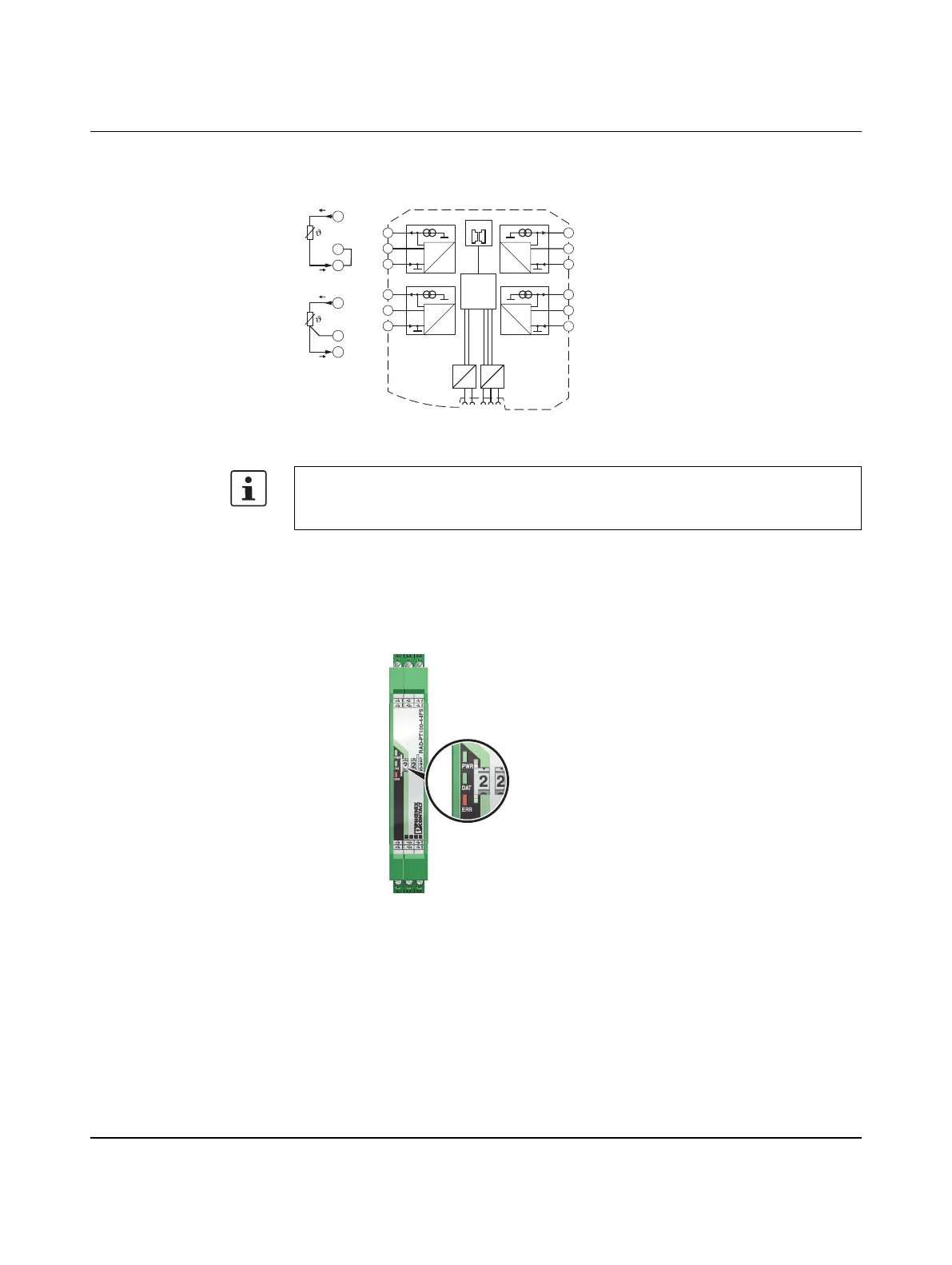
3.2.5 Basic circuit diagram
Figure 3-15 Basic circuit diagram for the RAD-PT100-4-IFS
3.2.6 Diagnostic LEDs
The RAD-PT100-4-IFS I/O extension module uses a total of three LEDs to indicate the
operating states.
Figure 3-16 Diagnostic LEDs of the RAD-PT100-4-IFS
PWR LED
The green PWR LED indicates the supply voltage status.
With 2-wire technology, you need an insertion bridge between terminals x.2 and x.3. In
this case, the measuring accuracy is reduced (see “Measuring errors using 2-wire
connection technology” on page 22).
OFF No supply voltage
ON Supply voltage OK
2.1
2.3
+I
1
-I
1
3-wire
2.2
-U
1
µC
2.1
2.2
2.3
3.1
3.2
3.3
5.1
5.2
5.3
4.1
4.2
4.3
IO-MAP
0
1
DC
DC
IFS
IFS
A
D
1mA
A
D
1mA
A
D
1mA
A
D
1mA
-I2
-U2
+I2
+I1
-U1
-I1
+I3
-U3
-I3
+I4
-U4
-I4
2.1
2.3
+I
1
-I
1
2.2
+I
1
2-wire

 Loading...