Description of I/O extension modules
3827_en_B PHOENIX CONTACT 37/138
I
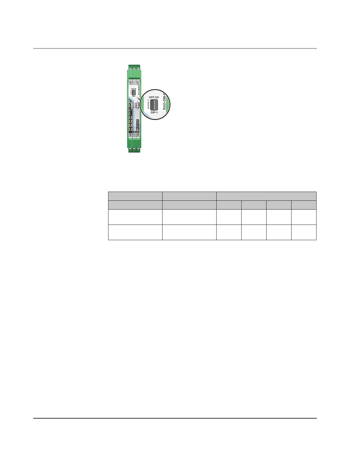
Figure 3-26 DIP switches of the RAD-DI8-IFS
• Use DIP switch 1 to select between static mode and pulse counter mode.
• Disconnect the device from the supply voltage.
• Switch the supply voltage back on.
• The selected mode is now active.
3.5.4 Functions in pulse counter mode
The counter state can only increase consecutively. When the maximum counter limit of
4,294,967,295 is reached, the counter is automatically set back to 0. In addition, you can
manually reset the counter states in three different ways:
Reset counter state via power up
• Disconnect the device power supply and then reconnect the voltage.
Reset counter state via the Modbus RTU register
• Reset the counter states via Modbus RTU as follows:
– DI1: bit 0 = 1 (register 40xx1)
– DI7: bit 1 = 1 (register 40xx1)
Table 3-8 DIP switches of the RAD-DI8-IFS
DIP switch
Input Output signal 1 2 3 4
Digital IN
DI1 ... DI8
Static mode OFF n.c. n.c. n.c.
Counter IN
DI1 + DI7
Pulse counter mode ON n.c. n.c. n.c.
n. c. = not connected, DIP switches 2 ... 4 have no function

 Loading...