Description of I/O extension modules
3827_en_B PHOENIX CONTACT 47/138
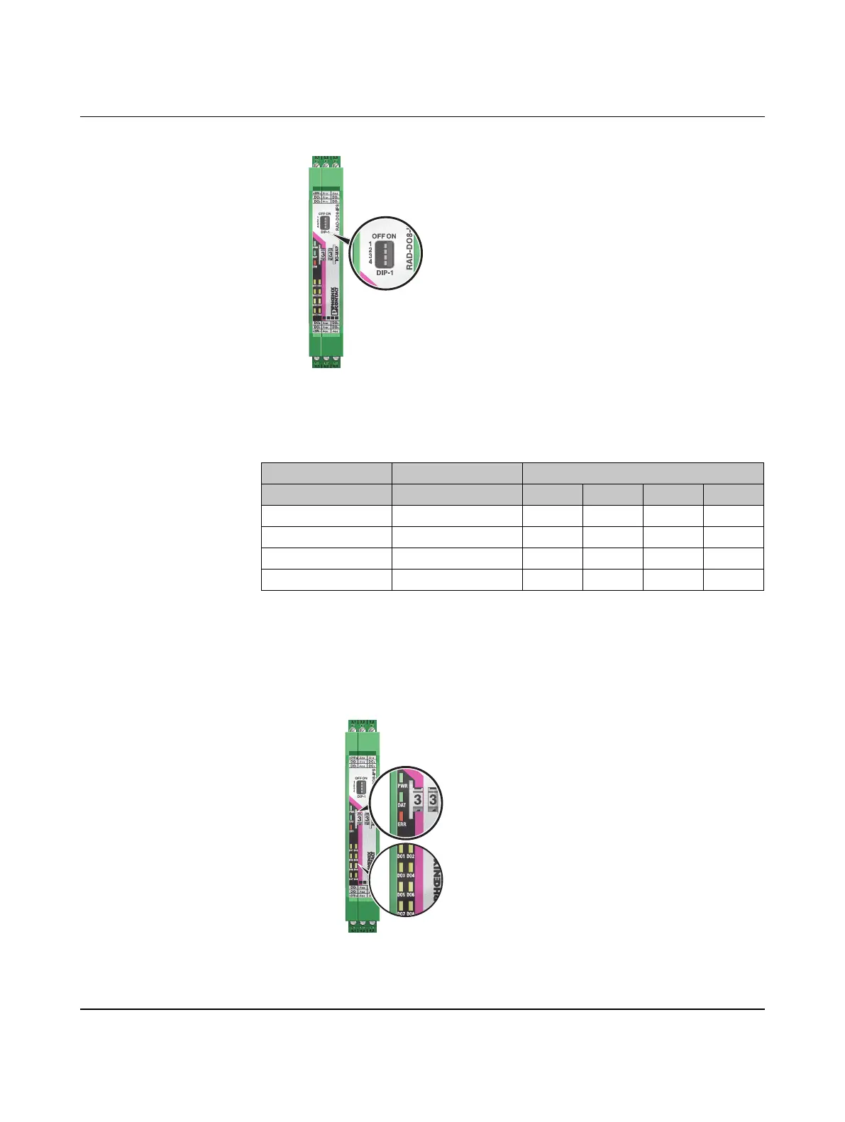
Figure 3-34 DIP switches of the RAD-DO8-IFS
3.7.4 Diagnostic LEDs
The RAD-DO8-IFS I/O extension module uses a total of eleven LEDs to indicate the
operating states.
Figure 3-35 Diagnostic LEDs of the RAD-DO8-IFS
Table 3-12 DIP switches of the RAD-DO8-IFS
DIP switch
Setting Output signal 1 2 3 4
Digital OUT 1 ... 4 RESET OFF n. c. n. c.
Digital OUT 1 ... 4 HOLD ON n. c. n. c.
Digital OUT 5 ... 8 RESET OFF n. c. n. c.
Digital OUT 5 ... 8 HOLD ON n. c. n. c.
n. c. = not connected, DIP switches 3 and 4 have no function

 Loading...