RAD-900-...
12/138
PHOENIX CONTACT 3827_en_B
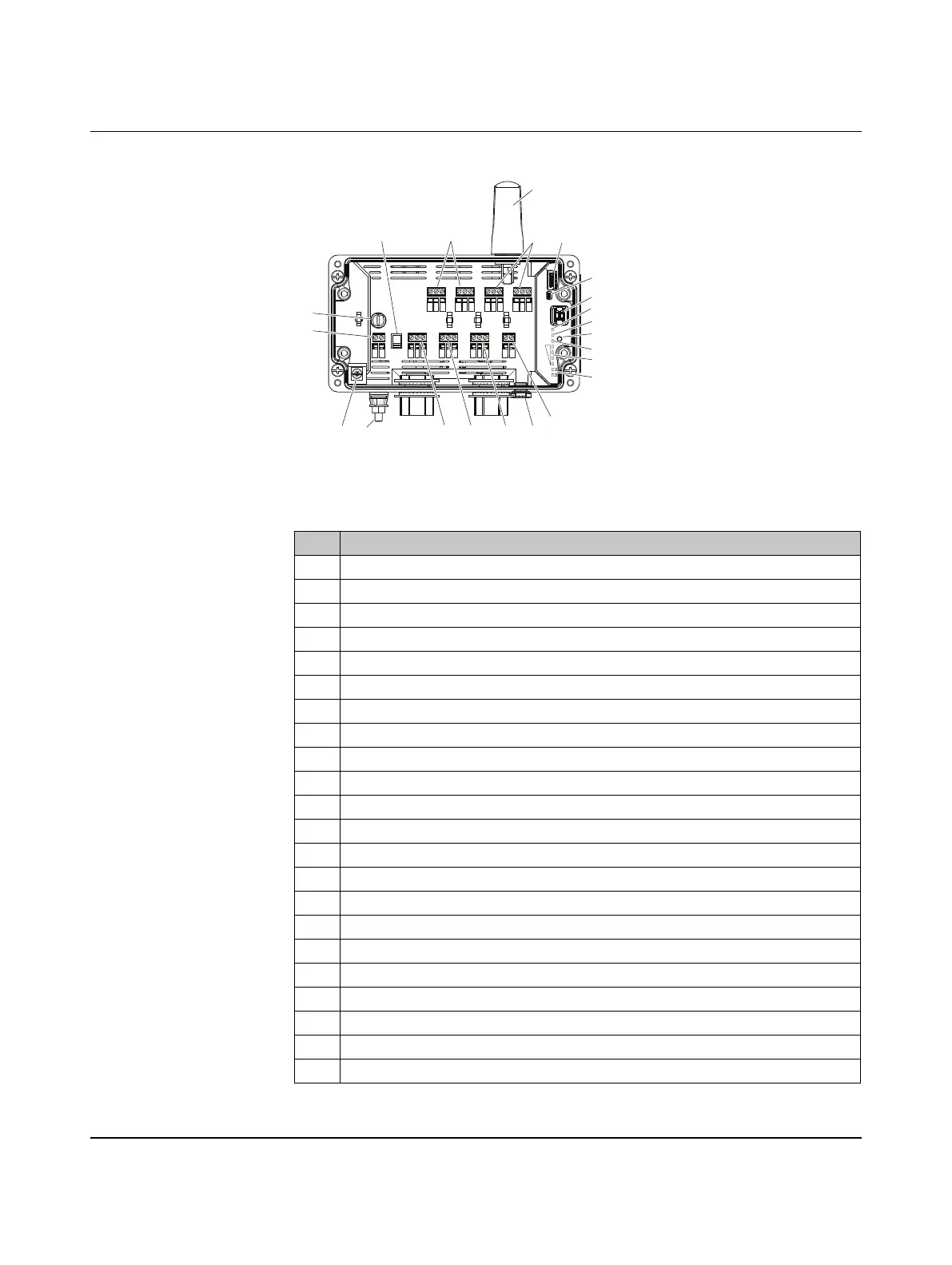
2.2.1 Structure
Figure 2-3 RAD-900-DAIO6 structure
Table 2-2 RAD-900-DAIO6 structure
Item Designation
1 N-type antenna
2 12-pos. programming interface (S-PORT)
3 DIP switches for configuring I/O
4 RAD ID address setting via thumbwheel
5 PWR status LED, green (supply voltage)
6 DAT status LED, green (I/O communication)
7 ERR status LED, red (communication error)
8 SET button
9 LED bar graph for displaying the wireless signal strength
10 Status LEDs of the digital VO
11 Relay output with floating PDT contact
12 Digital input as wide-range input
13 Analog input for 2-, 3-, and 4-wire measuring transducers
14 Analog output (current or voltage)
15 RF link
16 Test output RSSI (0...3 V DC) for evaluation of the wireless signal strength
17 Device supply (+24VDC/120 V AC, 0V/neutral)
18 Fuse
19 Power selection switch
20 Ground lug
21 Internal ground screw
22 Breather
ON-OFF
1 2
DIP
RSSI
ANALOG IN
ANALOG OUT
RF LINK
POWER
DC
FUSE
COM NO NC
DIGITAL OUT 2
DIGITAL OUT 1
DIGITAL IN 2
DIGITAL IN 1
COM NO NCLV HV COMLV HV COM COM NO NC
U I COM PWR +I -I + -+ -
230V
AC
RAD
ID
PWR
DAT
ERR
RF
LINK
SET
D1
D2
S-PORT
4-3-2-1
1
21112
3
4
5
6
7
8
9
10
131415
17
18
19
2021 22
16

 Loading...