Configuration and startup
3827_en_B PHOENIX CONTACT 81/138
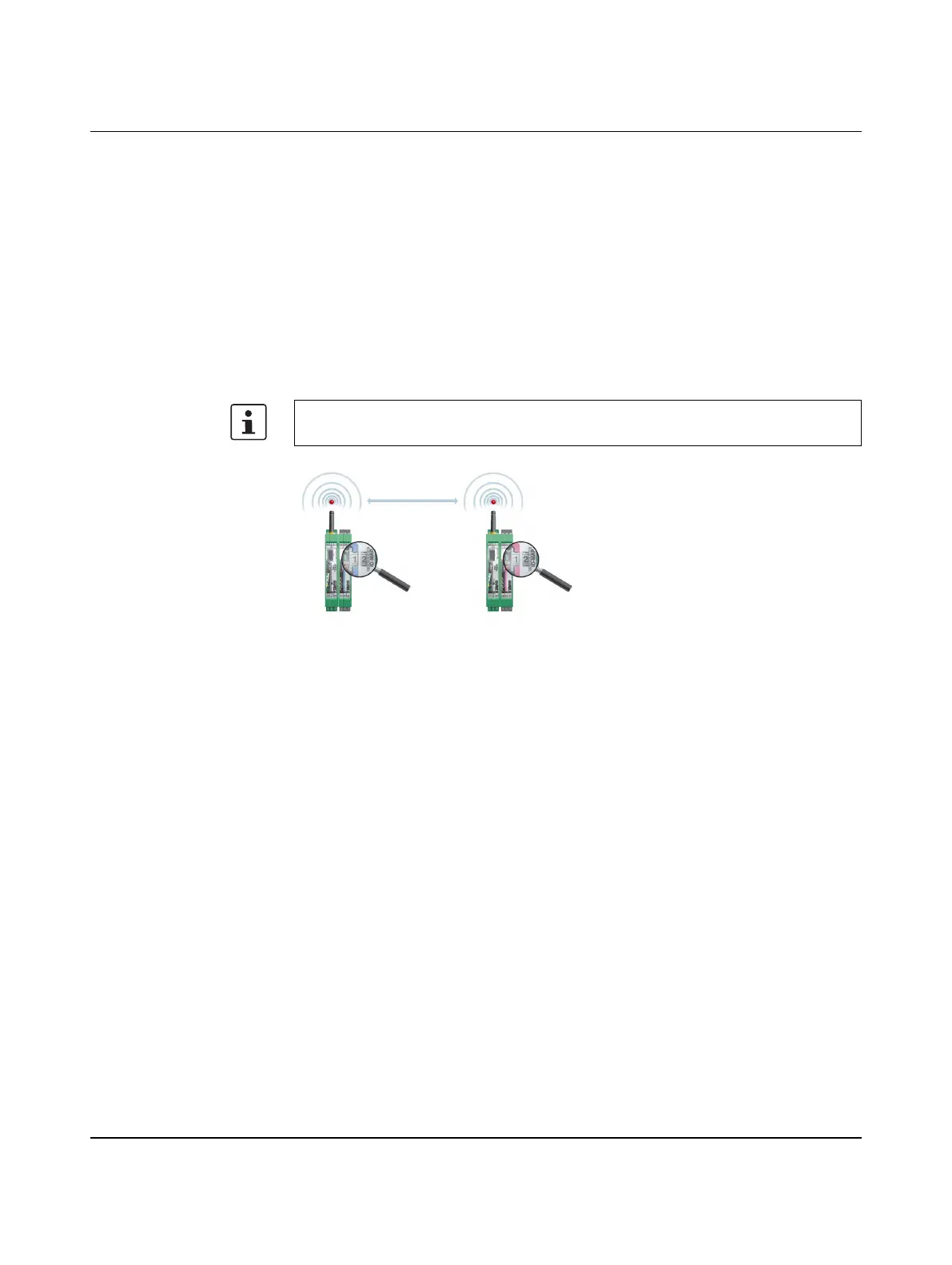
Wireless module in I/O data mode
– The input module must be provided with the same I/O-MAP address as the assigned
output module at the other wireless station (I/O mapping). Output modules with the
same I/O-MAP address may appear several times in the network at different stations.
– The I/O-MAP address of an input module may only appear once in the network.
– The channels of the input module are directly assigned to the channels of the output
module:
Figure 5-14 Input module and output module with the same address
Wireless module in PLC/Modbus RTU mode
– Output modules may not have the same I/O-MAP address as input modules. Exception:
Output modules with the same I/O-MAP address may appear several times in the
network at different stations.
– The I/O-MAP address of an input module may only appear once in the network.
– The input and output data is saved in a Modbus memory map in the master wireless
module. You can read or write the process data via the serial interface of the master
wireless module (RAD ID = 01) using the Modbus RTU command. The process data
tables can be found starting at “Modbus memory map” on page 100.
5.7.3 Wireless module in PLC/Modbus RTU dual mode
– Each wireless module may be assigned a Modbus address. The master wireless
module Modbus address may be changed from 01 if an existing Modbus device is
already assigned this address. A Modbus address may only appear once in the
network.
– Output modules may not have the same I/O-MAP address as input modules on a single
wireless device (station). Exception: Output modules with the same I/O-MAP address
may appear several times at the same station.
Input module Output module
Channel 1 Channel 1
Channel 2 Channel 2
... ...
It is not possible to individually assign the channels of the input and output modules.

 Loading...