RAD-900-...
62/138
PHOENIX CONTACT 3827_en_B
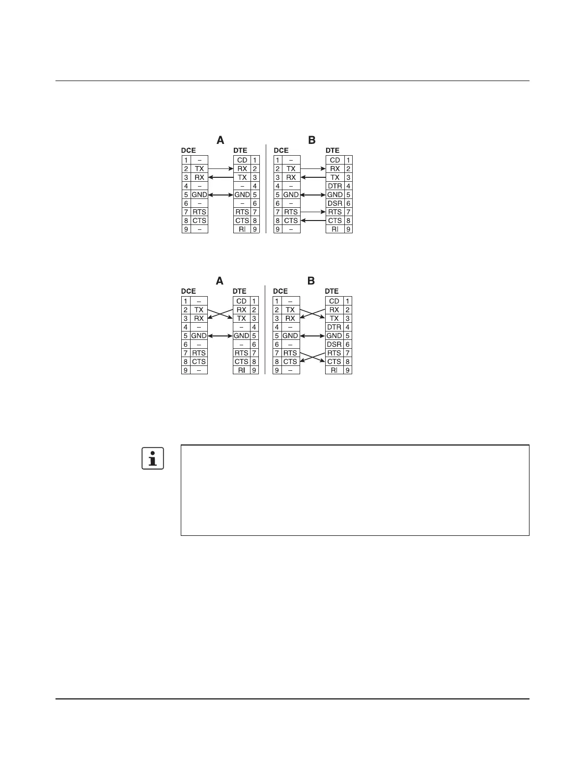
D-SUB 9 pin assignment
The RAD-900-IFS provides a D-SUB 9 female connector for attaching RS-232 serial
devices.
Figure 4-8 D-SUB 9 straight-through cable pinouts for 3-wire (A) and 5-wire (B)
Figure 4-9 D-SUB 9 null cable pinouts for 3-wire (A) and 5-wire (B)
4.1.5 Connecting the antenna
The wireless module is provided with an RSMA antenna socket for an external antenna.
Install the antenna outside the control cabinet or building.
Observe the installation instructions of the antenna and the “Installation and operation” on
page 6.
Observe the maximum permissible emitted transmission power of 36 dBm. The
transmission power can be calculated as:
device transmission power + antenna gain - cable attenuation
Reduce the device transmission power, if necessary.

 Loading...