RAD-900-...
24/138
PHOENIX CONTACT 3827_en_B
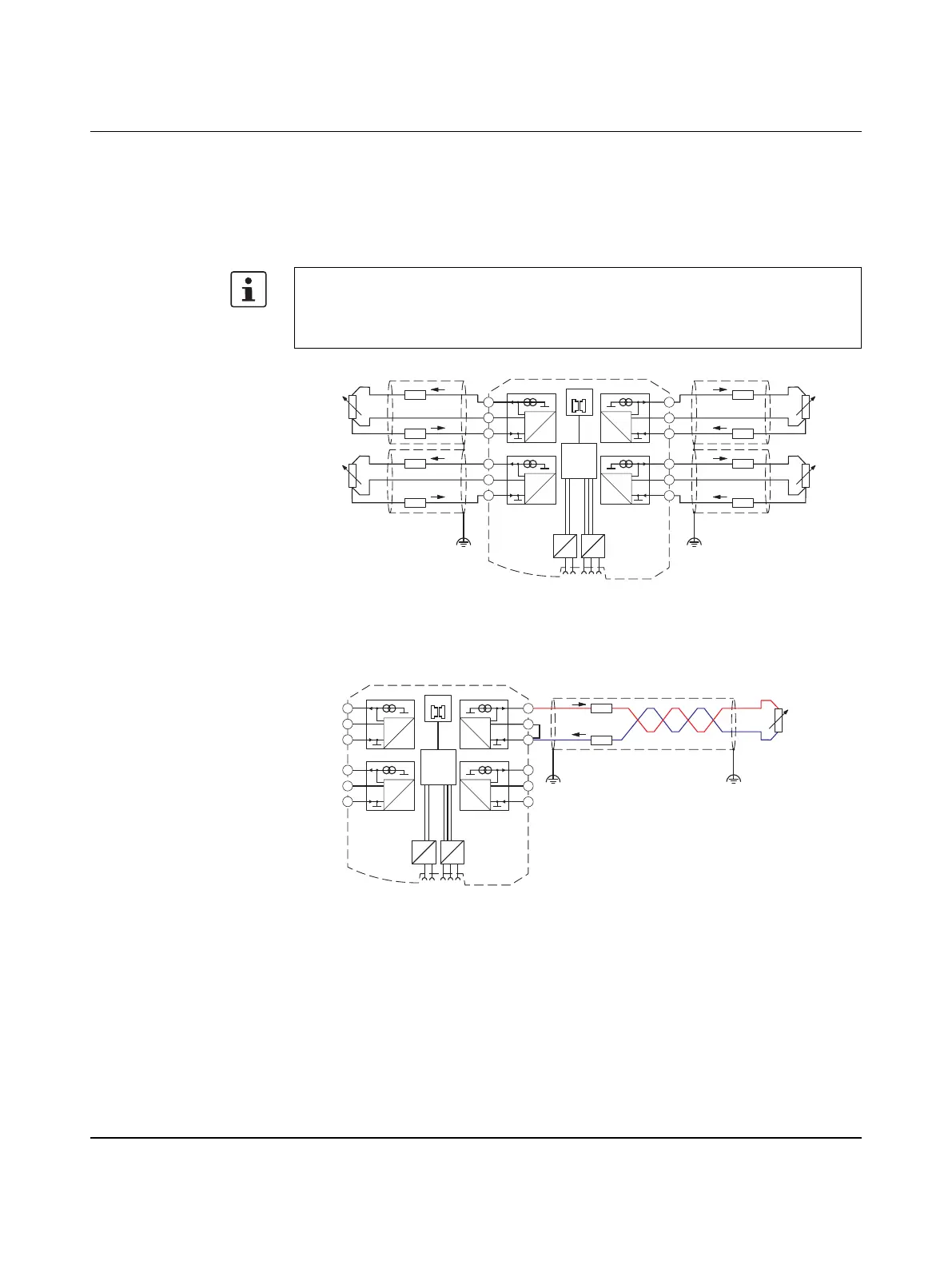
3.2.3 Shielding of the sensor cables
Always connect the analog sensors using shielded, twisted pair cables (e.g., LiYCY, TP
2 x 2 x 0.5 mm
2
).
• Immediately following entry in the control cabinet, connect the cable shields to the
corresponding shield connection clamps.
Figure 3-11 Shielding with 3-wire connection technology
2-wire connection technology with twisted pair cables and shielding
Figure 3-12 2-wire connection technology with twisted pair cables and shielding
Please note that the electrical isolation between the channels may no longer occur when
connecting the shields. The isolating distances between the individual channels need to
be re-evaluated after connecting the shields. The distances between the individual wires
and the common shields are crucial in this respect.
µC
2.1
2.2
2.3
3.1
3.2
3.3
5.1
5.2
5.3
4.1
4.2
4.3
IO-MAP
0
1
DC
DC
IFS
IFS
A
D
1mA
A
D
1mA
A
D
1mA
A
D
1mA
-I2
-U2
+I2
+I1
-U1
-I1
+I3
-U3
-I3
+I4
-U4
-I4
RL
I+
RTD
ϑ
RL
I–
U–
RL
I+
RTD
ϑ
RL
I–
U–
RL
I+
RTD
ϑ
RL
I–
U–
RL
I+
RTD
ϑ
RL
I–
U–
µC
2.1
2.2
2.3
3.1
3.2
3.3
5.1
5.2
5.3
4.1
4.2
4.3
IO-MAP
0
1
DC
DC
IFS
IFS
A
D
1mA
A
D
1mA
A
D
1mA
A
D
1mA
-I2
-U2
+I2
+I1
-U1
-I1
+I3
-U3
-I3
+I4
-U4
-I4
RL
RL
I+
I–
RTD
ϑ

 Loading...