RAD-900-...
36/138
PHOENIX CONTACT 3827_en_B
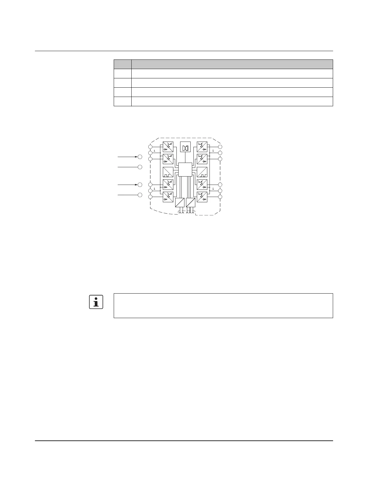
3.5.2 Basic circuit diagram
Figure 3-25 Basic circuit diagram for the RAD-DI8-IFS
3.5.3 Setting the DIP switches
You can use the DIP switches on the front to select between static mode or pulse counter
mode.
– In static mode, the DI1 ... DI8 inputs are activated, 0 V ... 30.5 V DC voltage.
– In pulse counter mode, the DI1 and DI7 pulse inputs are activated, 0 Hz ... 100 Hz
pulses.
11 CNT status LED, green (pulse counter mode)
12 ERR status LED, red (communication error)
13 DAT status LED, green (bus communication)
14 PWR status LED, green (supply voltage)
The pulse counter function is only available in PLC/Modbus RTU mode. Set the operating
mode using the PSI-CONF software (from Section 5.6, “Configuration via PSI-CONF
software” onwards).
Item Designation
0...100 Hz
2.1
2.2
GND
0...30,5 VDC
2.1
2.2
GND
µC
2.1
2.2
2.3
3.1
3.2
3.3
5.1
5.2
5.3
4.1
4.2
4.3
IO-MAP
0
1
DC
DC
IFS
IFS
CNT CNT
DI
2
DI
4
DI
1
DI
3
DI
8
DI
6
DI
7
DI
5
1-4
1-4
5-8
5-8
Pulse:
Static:

 Loading...