RAD-900-...
10/138
PHOENIX CONTACT 3827_en_B
2.1.1 Structure
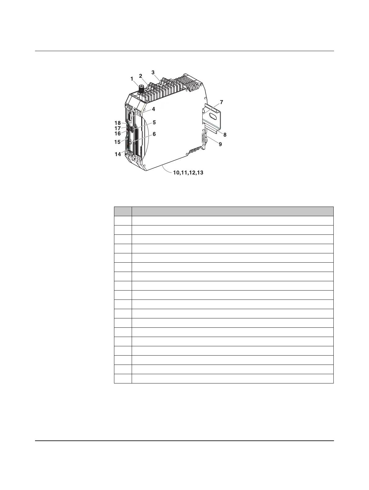
Figure 2-1 RAD-900-IFS structure
Table 2-1 RAD-900-IFS structure
Item Designation
1 RSMA antenna connection (socket)
2 Test output RSSI (0...3 V DC) for evaluation of the wireless signal strength
3 Device supply (+24VDC, 0V)
4 12-pos. programming interface (S-PORT)
5 RAD ID address setting via thumbwheel
6 SET button
7 Connection option for TBUS DIN rail connector
8 DIN rail
9 DIN rail release latch
10 Connection terminal block RS-485 interface
11 Connection terminal block RS-232 interface
12 Relay output with PDT contact (floating)
13 D-SUB 9 connector (RS-232 interface)
14 RS-232/485 serial interface status LED (RX/TX)
15 LED bar graph for displaying the wireless signal strength
16 ERR status LED, red (communication error)
17 DAT status LED, green (BUS communication)
18 PWR status LED, green (supply voltage)

 Loading...